
- SIGNA MR355 / SIGNA MR360
- Service Manual
- 5856356-3EN Revision 5.0
- Basic Service Documentation. Copyright General Electric Company.
- 00000018WIA30D50030GYZ
- id_131064281.2
- Jul 6, 2019 12:17:31 AM
Flow meter replacement
Prerequisites
| Required persons | Preliminary requirements | Procedure | Finalization |
|---|---|---|---|
| 1 | Not Applicable | - | Not Applicable |
| Item | Quantity | Effectivity | Part number | Manufacturer |
|---|---|---|---|---|
| Philips screwdriver | 1 | - | - | - |
| Flat-blade screw driver | 1 | - | - | - |
| Adjustable wrench | 2 | - | - | - |
| Gloves | 1 pair | - | - | - |
| Seal tape | 1 | - | - | - |
| Water container | 1 | - | - | - |
| Item | Quantity | Effectivity | Part number | Manufacturer |
|---|---|---|---|---|
| Flow meter | - | - |
5717574 | - |
| Condition | Reference | Effectivity |
|---|---|---|
|
System Power must be turned OFF. Refer to Lockout / Tagout for System Cabinet PDU Main Breaker | - | - |
About this task
Flow meter (PN#5717574, NITTO-KOHKI FM-03A FM-03B) set up as FRU, which can be used by certain plumbing assemblies listed See . FE can order flow meter instead of entire plumbing assemblyto do replacement.
| Flow meter | Plumbing assemblies | Description |
| 5717574 | 5343091 | PLUMBING ASSY MCS |
| 5343093 | PLUMBING ASSY - Facility Water | |
| 5343094 | PLUMBING ASSY 2-11kw chiller |
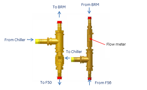
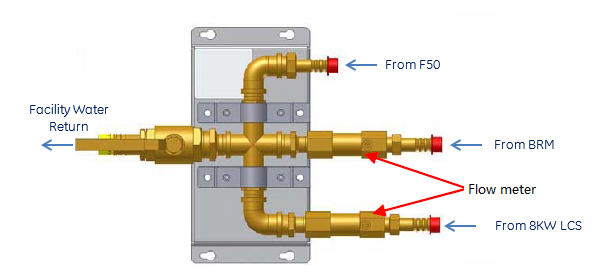
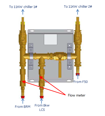
Note:
The flow should flow in the direction of the red arrows.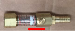
Built-in flow meter valve should be set in open position.
Procedure
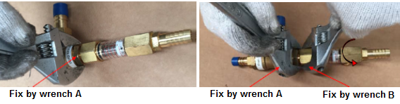
- Use wrench A to fix hex connector from tee joint side, and use
wrench B to fix hex connector of flow meter. Keep wrench A in original
place, then rotate wrench B to remove defect flow meter by anti-clockwise
direction turn.
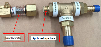
- Apply the seal tape on screw thread of tee joint with clockwise
direction turn, and then install new flow meter with tee joint together.
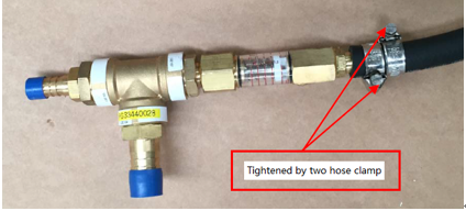
- Install hose pipe on hose nipple of new flow meter, then tighten
pipe by two hose clamps---one clams was tighten by position turn &
another clamps was tighten with inversion turn.
Finalization
No finalization steps.