- id_19633182
- Version: 4.4
- Date: Jan 16, 2020 3:43:12 PM
Applying LOTO - HEC
Prerequisites
| Personnel requirements | |||
|---|---|---|---|
| Required persons | Preliminary requirements | Procedure | Finalization |
| 1 | - | 10 minutes | - |
| Tools and test equipment | |||
|---|---|---|---|
| Item | Quantity | Part number | Manufacturer |
| RED Logout Tagout Lock with Each Lock Uniquely Keyed | 3 | 5451778 | - |
| Multi-Locking Device (if multiple service personnel are involved) | 1 to 3 (up to three may be necessary if the valve LOTO devices support only one lock) | 46-194427P313 | - |
| Red Warning LOTO Tag | 3 | 46-194427P322 | - |
| Digital Voltmeter (DVM) | 1 | 46-194427P284 | - |
| Ball Valve LOTO Device | 2 | 5372868 | - |
| Safety |
|---|
|
Before working in any GE Healthcare MR suite or performing any GE Healthcare service procedure, you must:
If you have any safety concerns at any time, do not begin work or immediately stop work and move to a safe location. Immediately contact your supervisor or site safety officer for instructions on how to proceed. |
|

| Affected by LOTO | ||||
|---|---|---|---|---|
| Name of equipment | Number of locks | Titles of employees authorized to perform LOTO | Titles of affected employees | How to notify |
|
1 per GE field engineer (FE) | GE Field Engineers | Hospital personnel | Verbal, posted signs |
note: The following table describes the type, location, and magnitude of energy to be LOTO’d.
| Energy Source | Yes | No | Location of Energy Isolating Means | Magnitude of Energy |
|---|---|---|---|---|
| Electrical | x |
|
380 to 480 VAC | |
| Pneumatic | x | |||
| Hydraulic | x | |||
| Gas/Water/Steam | x | |||
| Chemical | x | |||
| Mechanical Motion | x | |||
| Gravity | x | |||
| Springs | x | |||
| Thermal | x | |||
| Stored Energy | x | |||
| Air Under Pressure | x | |||
| Oil Under Pressure | x | |||
| Water Under Pressure | x | Facility water valves at top of HEC and MDP circuit breaker panel |
|
|
| Gas Under Pressure | x | Valves on ends of cryocooler helium lines – valves close automatically when disconnected | ||
| Steam | x | |||
| Other | x |
Types of equipment and/or methods selected to dissipate or isolate stored energy
Type(s) of equipment and/or method(s) used to ensure disconnection(s)
Procedure
- Apply LOTO to the MDP:
- Notify affected personnel that LOTO will be applied.
- On the front of the HEC, look at the variable speed drive displays to visually make sure that the power is on. If power is off, proceed to Step 1.e.
Figure 1. HEC variable speed drive displays
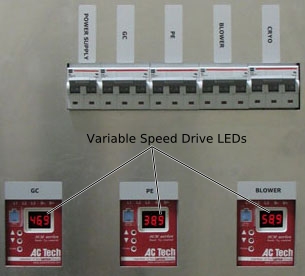
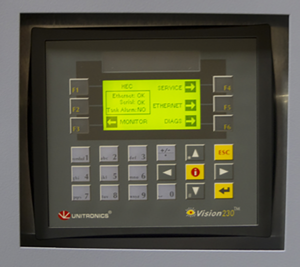
- note: Powering off HEC without first powering down pumps from VFD can put the VFD at risk of damage.Toggle off the pumps and blower with the PLC Signal Box keypad as follows:
- Blower: Press and hold the up-arrow ( ^ ), and press F1
- Gradient Coil Pump: Press and hold the up arrow ( ^ ), and press F2
- Power Electronics: Press and hold the up arrow ( ^ ), and press F3
Figure 2. PLC signal box
- Make sure the VFD LEDs read zero before proceeding.
- Turn off all five circuit breakers on the HEC power box. The circuit breakers are located above the variable speed drive displays.
- notice
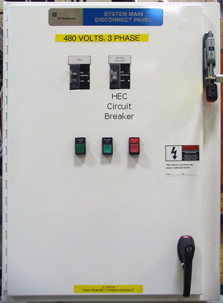
- note: If the customer has supplied the MDP, see the MDP manual for information about LOTO for the HEC circuit breaker.At the front of the MDP, move the HEC circuit breaker to the OFF position and apply LOTO.
Figure 3. HEC circuit breaker (example)
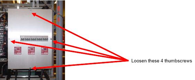
- Make sure all energy is dissipated. Carefully remove the four thumbscrews securing the HEC power box front cover and remove the cover.
Figure 4. Location of screws on HEC power box
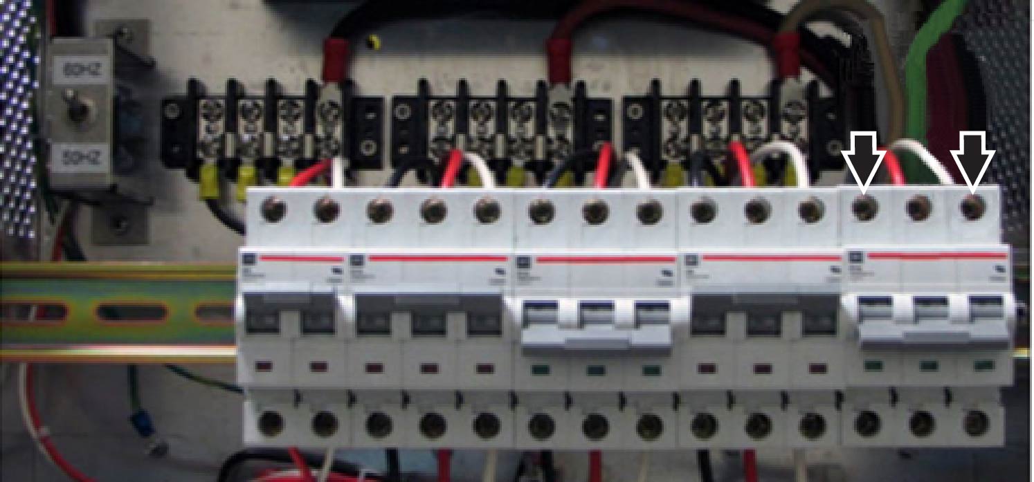
- Make sure voltage is removed by testing the line-to-line voltage at the top of the breaker points.
Figure 5. Terminal points of HEC power box
- Replace the power box front cover.

- Apply LOTO to the HEC shut-off valves:
- Prepare for shut down. Check with the facility owner to determine the proper shutdown method for the chiller.
- Shut off both the facility return and supply valves by turning the handle to a 90º angle.
- Apply LOTO device to both the return and supply valves.
Figure 6. LOTO installed on return valve
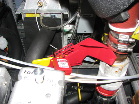
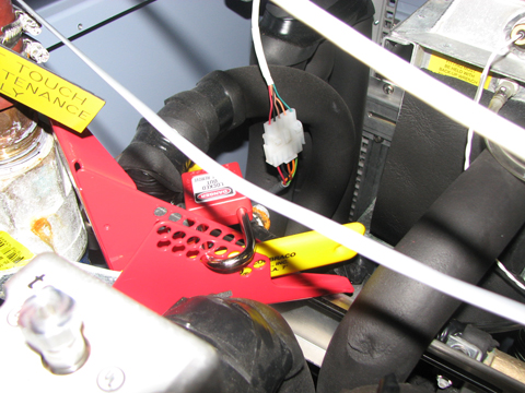
Figure 7. LOTO installed on supply valve
- Drain the fluid between the return and supply lines. Refer to Coolant Draining in the Service Methods manual for the system.
- Make sure there is no water draining from quick disconnect and pressure in the line is relieved.