- id_2019791
- Version: 2.0
- Date: Oct 13, 2019 9:24:38 PM
Checking the response pads
Procedure
- In the command prompt, type: screen /dev/ttyCedrusLumina. The BrainWave terminal opens. Use this window to complete BrainWave hardware function checks.
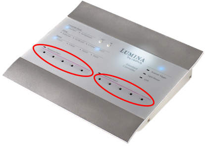
- Press the response pad buttons in the magnet room while an independent observer in the control room confirms that the R/G/B/Y LEDs on the response interface box respond accordingly.
Figure 1. Cedrus Lumina 3G response pad LEDs
 note: Only the Cedrus Lumina 3G is supported. The Cedrus Lumina LP400 should not be plugged into the GOC.
 - If the LEDs do not respond correctly:
- Make sure there is continuity between the response pads and the controller:
- Check that the response interface box has power.
- Check that the response fiber optic cable is properly connected at the response interface box and the response pad assembly, as well as at the mating connection.
- If the LEDs do not light, check the cabling between the response pads in the magnet room and the controller in the control room.
- Make sure there is continuity between the response pads and the controller:
- Press the response pad buttons in the magnet room.
- Make sure the following Cedrus box LEDs illuminate and the terminal window shows the corresponding values. This makes sure there is communication from the response pads in the magnet room to the controller box, and then to the host PC. If there is no response on the host PC, check the USB cable between the controller box and the host PC:
Table 1 Response button functional check Response pad button color pressed Cedrus box LED illuminated Character shown on terminal screen Blue 1 a Yellow 2 b Green 3 c Red 4 d