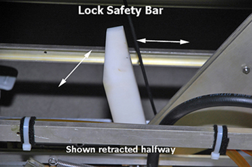
When doing maintenance on the table in its up position, severe personal injury can occur if the table is accidentally lowered during maintenance.
Make sure the lock safety bar is safely in place.
Lower the table lock safety bar, then lower the table to make sure weight is resting on the safety bar.
Figure 1. Table lock safety bar
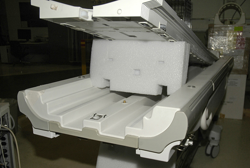
Release the cradle and manually slide the cradle forward. Prop it up for access to the table top height adjustment screw, or remove the cradle completely. For more information, see Removing Cradle Assembly.
Figure 2. Propping up cradle
Use a flat-blade screwdriver to remove the cover plug from the table top height adjustment screw.
Put a piece of tape over part of the e-clip to prevent it from becoming lost during removal. Use needle-nose pliers to remove the clip from the end of the adjustment screw.
If the cradle was not removed, slide the cradle back onto the table.
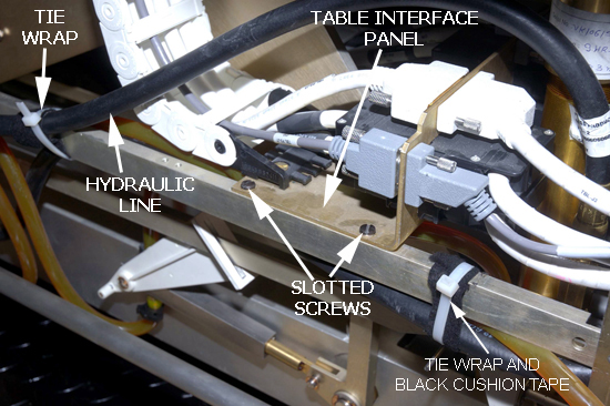
If a table interface panel (TIP) is present at the lower front of the table chassis, remove the right and left slotted screws from the TIP.
Freeing the TIP allows backward movement of this panel 2 to 3 inches and angling it up, allowing easier access to unscrew the cable connectors.
Figure 3. TIP on right side of table chassis
Remove the tie wrap and black cushion tape from the hydraulic line.
Notice
If a TIP is present, avoid stripping the lightweight aluminum screws when disconnecting the black cable connectors from the TIP.
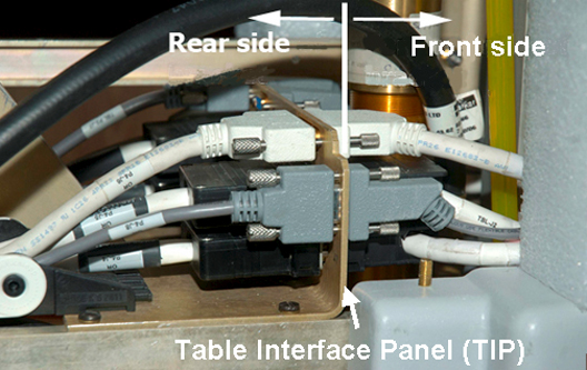
If a TIP is present on right side of table chassis, remove all front side cable connectors from the TIP, and secure them out of the way to fully expose the base of the hydraulic cylinder.
Removing the cable connectors on the right side of the table provides the best access to the hydraulic cylinder base.
Figure 4. Location of cable connectors on front side of panel
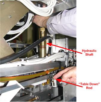
While moving the table down valve to the rear of the table, pull down on the hydraulic cylinder until it is fully retracted.
Figure 5. Hydraulic shaft
Remove the up sensor bracket.
Put sufficient absorbent towels underneath the work area.
Disconnect the black hydraulic line from the base of hydraulic cylinder using two 3/4 inch open-end wrenches, then fasten the line up and to the side to avoid excess spillage. To prevent oil from draining from the reservoir, clamp the clear tube, remove the black clamp, then remove the clear tube.
Remove the e-clip from the end of the cylinder mounting pin, located at base of the cylinder assembly.
Line up the cutout on the caster linkage with the pin, and slide the cylinder mounting pin out from the base of the hydraulic cylinder.
Note: Use the brake pedal to engage brakes.
Remove the hydraulic cylinder from the base of the table chassis by angling the cylinder top toward the rear while lifting the base up and out. Be careful of the linkage attached to the down valve.
Remove the up sensor collar by pressing the pin out.