- Optima MR450w BASE 1.5T System Service Methods
- 5690012-2EN Revision 3
- 00000018WIA3045A030GYZ
- id_123748761.12
- Aug 14, 2019 8:02:18 PM
Touch-n-Go (TnG) strip and side bumper replacement
Prerequisites
| Required persons | Preliminary requirements | Procedure | Finalization |
|---|---|---|---|
| 1 | - | 75 minutes | - |
| Item | Quantity | Effectivity | Part number | Manufacturer |
|---|---|---|---|---|
| 5/32 inch Allen wrench | 1 | - | - | - |
| 3/8 inch open end wrench | 1 | - | - | - |
| Medium Phillips screwdriver | 1 | - | - | - |
| Item | Quantity | Effectivity | Part number | Manufacturer |
|---|---|---|---|---|
| Front RH TnG Assembly | 1 | - |
See FRU manual. | - |
| Arm Board TnG Assembly | 1 | - |
See FRU manual. | - |
| Rear RH TnG Assembly | 1 | - |
See FRU manual. | - |
| Front LH TnG Assembly | 1 | - |
See FRU manual. | - |
| Arm Board TnG Assembly | 1 | - |
See FRU manual. | - |
| Rear LH TnG Assembly | 1 | - |
See FRU manual. | - |
| Front RH Side Bumper | 1 | - |
See FRU manual. | - |
| Arm Board Bumper (use for RH or LH side) | 1 | - |
See FRU manual. | - |
| Rear RH Side Bumper | 1 | - |
See FRU manual. | - |
| Rear RH Side Bumper for OR-Compatible Table | 1 | - |
See FRU manual. | - |
| Front LH Side Bumper | 1 | - |
See FRU manual. | - |
| Rear LH Side Bumper | 1 | - |
See FRU manual. | - |
| Rear LH Side Bumper for OR-Compatible Table | 1 | - |
See FRU manual. | - |
About this task
Overview
On each side of the patient table along the top edge, there are Touch and Go (TnG) strips that run the length of the table. A closer look at the TnG strips internally shows that each side is made up of three individual strips connected by jumpers. If one of the strips fails, replace only that specific strip. In other words, you do not have to replace the entire side. Be certain of which strip you are replacing because each one has a separate part number. See the Table 3 section for all part numbers.
This procedure also covers replacing the table side bumpers. The convenience of replacing any of the three side bumpers on either side of the table is that a TnG strip is contained within a side bumper. Therefore, whether you need to replace a TnG strip or a side bumper, you need to remove the TnG strip from its respective side bumper.
Procedure
- Undock the patient table and move it out of the magnet room.
Figure 1. Table covers 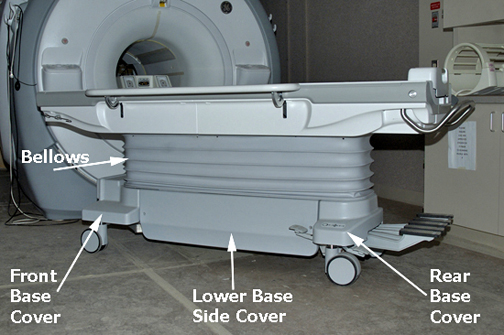
- At the front of the table, remove the front bottom cover (4
screws).
Figure 2. Front Bottom Cover 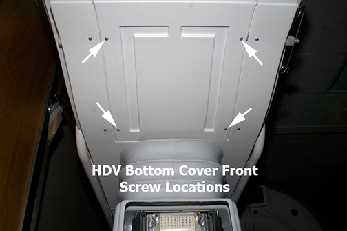
- (Skip this step for tables without TnG strips.) To remove the table handle, at the foot of the table rotate the handle down by pushing the silver button on the left side of the table to release the table. Use a 5/32 inch Allen wrench to remove hex socket screws, one on each side, from the table handle. Push the silver button again to rotate the handle back up to allow the handle to slip off.
Figure 3. Table Handle in Down Position 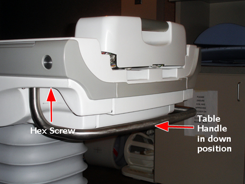
- Note: Side cover removal: Determine which TnG strip or side bumper to replace, and then pay attention to the following:On the bottom right or left side of the table, remove the appropriate side cover screws and then slide the side cover down.
- If replacing the front TnG strip or side bumper, remove the front table side cover (4 screws).
- If replacing the middle TnG strip or side bumper, remove both front and rear table side covers (8 screws).
- If replacing the rear TnG strip or side bumper, remove the rear table side cover (4 screws).
Figure 4. Side cover, bottom side screws 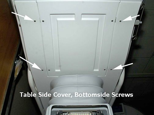
Figure 5. Side cover, bottom side screws 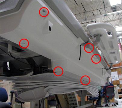
- Use a 3/8 inch open end wrench to remove nuts and washers from the appropriate front, middle, or rear TnG strip/side bumper studs.
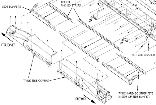
Figure 6. Side cover, side bumper, TnG strip diagram