
- Optima MR450w BASE 1.5T System Service Methods
- 5690012-2EN Revision 3
- 00000018WIA3008BE20GYZ
- id_131058183.0
- Aug 29, 2019 1:57:42 AM
Cradle Assembly Removal and Replacement
Prerequisites
| Required persons | Preliminary requirements | Procedure | Finalization |
|---|---|---|---|
| 1 | Not Applicable | See Procedure Overview minutes | Not Applicable |
| Item | Quantity | Effectivity | Part number | Manufacturer |
|---|---|---|---|---|
| Non-ferrous tool kit | 1 | - |
5113258 or 5112581 | - |
| Wood blocks or similar non-ferrous material for propping up cradle | As needed | - |
N/A | - |
| Item | Quantity | Effectivity | Part number | Manufacturer |
|---|---|---|---|---|
| Loctite 242 | 0.5 CC | - |
46-170686P1 | - |
| Item | Quantity | Effectivity | Part number | Manufacturer |
|---|---|---|---|---|
| 16-Channel Cradle Assembly, non-electrical | N/A | Curved non-electrical table |
See FRU Manual | - |
| Cradle Assembly | N/A | Curved 32-channel table |
See FRU Manual | - |
About this task
Procedure Timing (minutes):
- Non-electrical table: 15
- 32-channel curved table: 30
Not all tables are valid on all systems.
Choose the correct procedure for the type of table you are servicing:
- Non-electrical table: Removing Cradle from Curved Non-Electrical Patient Table
- 32-channel curved table: Removing Cradle from Curved 32-Channel Table
Note: Photographs are for illustration purposes only and may not show the same table you are servicing.
Removing Cradle from Curved Non-Electrical Patient Table
About this task
Procedure
- At the same time, press the cradle latch block and push in the cradle release button at the front of the cradle.
Figure 1. Cradle removal 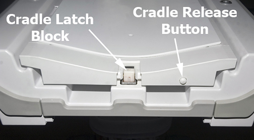
Push in the right actuator on the table front base.CAUTION 
Figure 2. Table Front Base 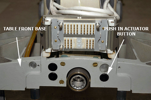
- Note: Pressing the actuator button engages the secondary cradle latch cable and causes the pin stop to move down flush with the table top surface, allowing the cradle to slide forward.Prop up the cradle or remove the cradle from the patient table to perform desired maintenance.
Figure 3. Propping Up Front of Cradle 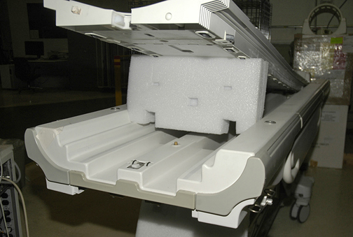
Removing Cradle from Curved 32-Channel Table
About this task
This procedure describes how to release and remove the cradle from the patient table and how to replace it. Whether you choose to remove the table from the magnet room depends entirely on your service needs.
Procedure
- At the same time, press the cradle latch block and push in the cradle release button at the front of the cradle.
Figure 4. Cradle Removal
Push in the right actuator on the table front base.CAUTION Figure 5. Table Front Base Pressing the actuator button engages the secondary cradle latch cable and causes the pin stop to move down flush with the table top surface, allowing the cradle to slide forward.
- Remove the cradle in part or in full, as needed:
- If you do not need to fully remove the cradle:
-
Slide the cradle forward far enough to clear the cradle guide rail latches at the rear of the table.
-
Use wood blocks (or similar) to prop up the front of the cradle.
Figure 6. Propping up Front of Cradle
-
- If you do not need to fully remove the cradle:
Replacing P-Port Covers
Procedure
- Each P-port cover (front and rear) is attached by a rubber tether. Remove the P-port cover by gently tugging its tether to pull it out.
- Replace with a new P-port cover, gently pushing its rubber tether into place.
Finalization
Procedure
- Dock the table.
- Confirm that the cradle release functions properly.
- Confirm that the LPCA connects to the cradle and that the cradle can move into the bore.