- Optima MR450w BASE 1.5T System Service Methods
- 5690012-2EN Revision 3
- 00000018WIA3046BE20GYZ
- id_131071132.22
- Apr 23, 2020 7:30:25 PM
Patient Table Braking System Replacements
Prerequisites
| Required persons | Preliminary requirements | Procedure | Finalization |
|---|---|---|---|
| 1 | Not Applicable | 30-60 minutes | 5 minutes |
| Item | Quantity | Effectivity | Part number | Manufacturer |
|---|---|---|---|---|
| Non-Magnetic Tool Kit | 1 | - |
5113258 or 5112581 | - |
| Item | Quantity | Effectivity | Part number | Manufacturer |
|---|---|---|---|---|
| Cable Ties | As needed. | - | - | - |
| Loctite 242 | 0.5 CC | - |
46-170686P1 | - |
| Item | Quantity | Effectivity | Part number | Manufacturer |
|---|---|---|---|---|
| Shoulder Screw, IN ¼-20 x 3/8, SS18-8 | 3 | - |
See itemized Table parts list in FRU Manual. | - |
| Shoulder Screw, IN ¼-20 x 5/8, SS18-8 | 2 | - |
See itemized Table parts list in FRU Manual. | - |
| Nylon Washer | 9 | - |
See itemized Table parts list in FRU Manual. | - |
| Rubber Washer | 1 | - |
See itemized Table parts list in FRU Manual. | - |
| Shaft Linkage-Right | 1 | - |
See itemized Table parts list in FRU Manual. | - |
| Shaft Linkage-Left | 1 | - |
See itemized Table parts list in FRU Manual. | - |
| Link - Reversing | 1 | - |
See itemized Table parts list in FRU Manual. | - |
| Link - Left Rear | 1 | - |
See itemized Table parts list in FRU Manual. | - |
| Link - Left Front | 1 | - |
See itemized Table parts list in FRU Manual. | - |
| Link - Right Rear | 1 | - |
See itemized Table parts list in FRU Manual. | - |
| Link - Right Front | 1 | - |
See itemized Table parts list in FRU Manual. | - |
| Bearing IGUS MCI-12-02 | 4 | - |
See itemized Table parts list in FRU Manual. | - |
| Shaft Extension | 2 | - |
See itemized Table parts list in FRU Manual. | - |
| Mounting Block | 1 | - |
See itemized Table parts list in FRU Manual. | - |
| Pin - Actuator | 4 | - |
See itemized Table parts list in FRU Manual. | - |
| ||||
About this task
This procedure explains how to replace various components in the Table braking system and various braking system checks at the completion of the replacements. The replacements and functions covered in this document include:
Shaft Linkage-Right, Shaft Extension, and Bearing IGUS Replacement
Caster Pin Actuator Replacement
Left rear brake link replacement
Right rear brake link plate replacement
Front left and right brake link plate replacement
Step 3 (Braking system checks)
Shaft Linkage-Right, Shaft Extension, and Bearing IGUS Replacement
About this task
This procedure is written for the right side of the Table. The procedure for the left side of the Table, as seen in Figure 1, is similar.
Shaft Linkage-Right, Shaft Extension, and Bearing IGUS Removal
Procedure
- Undock the Table and remove it from the magnet room.
Figure 1. Table Covers 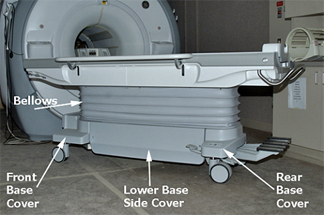
- Remove Front and Rear Base Covers by removing the two front
screws and the two screws that attach the Bellows.
Figure 2. Rear Base Cover 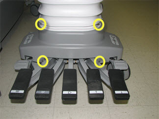
- Lower the Table’s Lock Safety Bar. Lower the Table to
ensure all weight is resting on the lock bar.
Figure 3. Table Lock Safety Bar 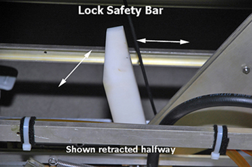
Figure 4. Isometric Assembly 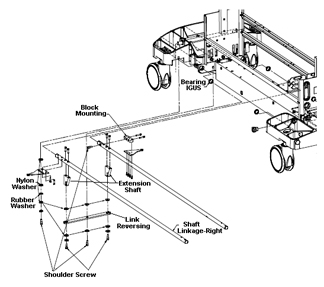
- Remove the screws that attach the Shaft Linkage-Right to the
Link-Right Rear, located at the right rear side of the Table. Also
remove the two screws that attach the Link-Right Front on the opposite
side of the Table in the same location.
Figure 5. Shaft Linkage, Right Rear 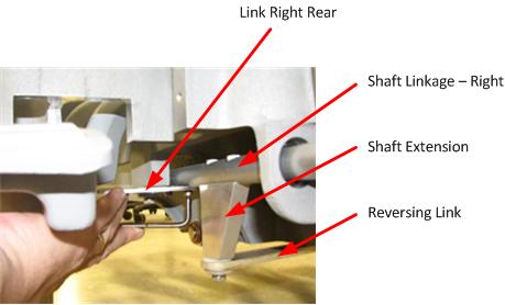
- Remove the Shaft Extension from the Shaft Linkage Right.
- Remove the shoulder screw, as shown below.
Figure 6. Removing the Shoulder Screw 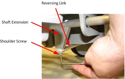
- For best access to Shaft Extension mounting screws, put the
Table brake in "free rotate" position.
Figure 7. Brake Positions 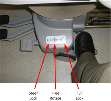
- Remove the Shaft Extension mounting screws. (If more space is
needed to access the Shaft Extension mounting screws or for better
torque, rotate the bottom of the Shaft Extension out.)
Figure 8. Shaft Extension Mounting Screws 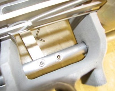
Figure 9. Removing Shaft Extension Screws 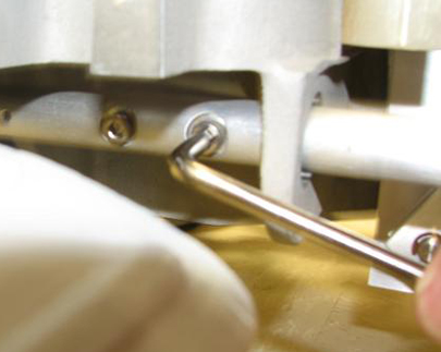
- Remove the shoulder screw, as shown below.
- Press the lower pedal to create space to remove the Shaft Linkage
through the rear of the Table.
Figure 10. Removing the Shaft Linkage 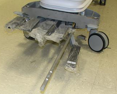
- If replacing front or rear bearing IGUS, remove the bearing
IGUS by hand and replace as required.
Figure 11. Bearing IGUS 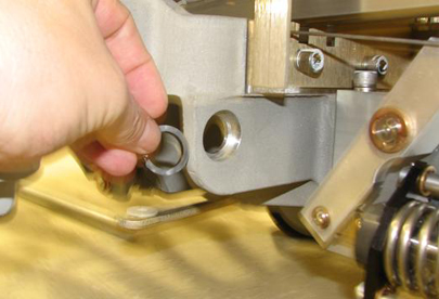
Shaft Linkage-Right and Shaft Extension Installation
Procedure
- Press the lower pedal to create space and replace the Shaft Linkage through the rear of the Table.
- Replace the Shaft Extension in the Shaft Linkage Right.
- For best access to Shaft Extension mounting screws, put the Table brake in "free rotate" position.
- Replace the Shaft Extension mounting screws. (If more space is needed to access the Shaft Extension mounting screws or for better torque, rotate the bottom of the Shaft Extension out.) Apply Loctite when reinstalling the mounting screws.
- Replace the shoulder screw.
- Replace the screws that attach the Shaft Linkage-Right to the Link-Right Rear, located at the right rear side of the Table. Also replace the two screws that attach the Link-Right Front on the opposite side of the Table in the same location.
- Raise the Table and raise the Lock Safety Bar for normal operation.
- Replace both the Front and Rear Base Covers. Reinstall the two front screws and the two screws that attach the Bellows.
- Replace both Lower Base Side Covers. Reinstall the two screws that fasten each Cover to the Table assembly. Note that Velcro strips attach the Lower Base Side Covers to the Bellows.
Reversing Link Replacement
Procedure
Mounting Block Replacement
Caster Pin Actuator Replacement
About this task
The pin actuator is a threaded pin that bolts into the caster arm.
Procedure
- Loosen and remove the caster pin actuator. See the following
illustration.
Figure 13. Caster Pin Actuator 
Left rear brake link replacement
Procedure
- Loosen the bolts securing the brake pedals to the cross bar of the pedal rod assembly.
Figure 14. Pedal rod bolts 
- Squeeze the left pedal and brake plate extension tight against the table frame.
Figure 15. Pedal rod adjustment 
- Remove the four screws and four washesrs securing the left rear brake link plate to the mounting block.Note: Discard the four removed screws.
Figure 16. Left rear brake link plate mounting 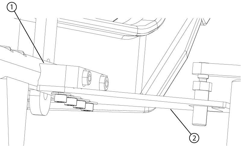
1 Mounting block 2 Link - Align the brake link plate as follows:
Figure 17. Left rear link alignment (view from the top) 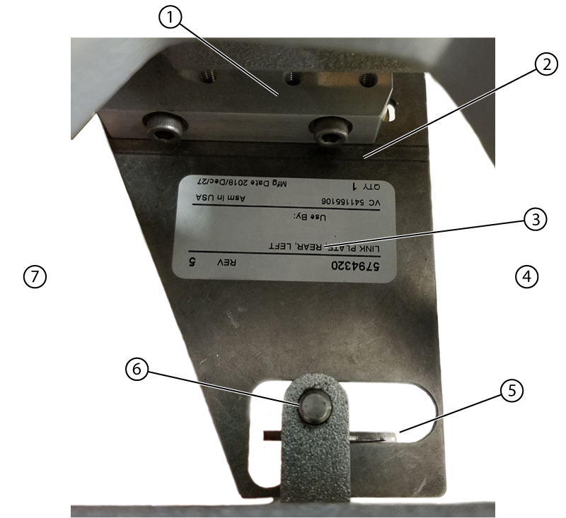
1 Mounting block 2 Scribe line 3 Link plate 4 Handle side 5 Shim 6 Caster pin 7 Dock side - Push the brake link plate towards the rear (handle end) of the table until it stops.
Figure 18. Slot position B 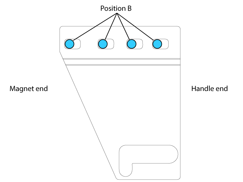
- Lift up on the end of the brake linkage plate until it is horizontal to the ground. Continue holding everything in position until the screws are tightened.
Figure 19. Left rear link alignment isometric view 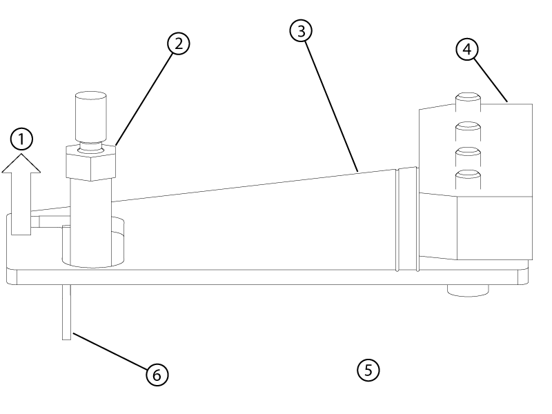
1 Lift up 2 Caster pin 3 Left rear link 4 Mounting block 5 Handle end of the table 6 Shim
- Push the brake link plate towards the rear (handle end) of the table until it stops.
Right rear brake link plate replacement
Procedure
- Install the right rear link plate with the open side of the caster pin hook towards the front of the table.
Figure 20. Right rear brake link plate (view from the top) 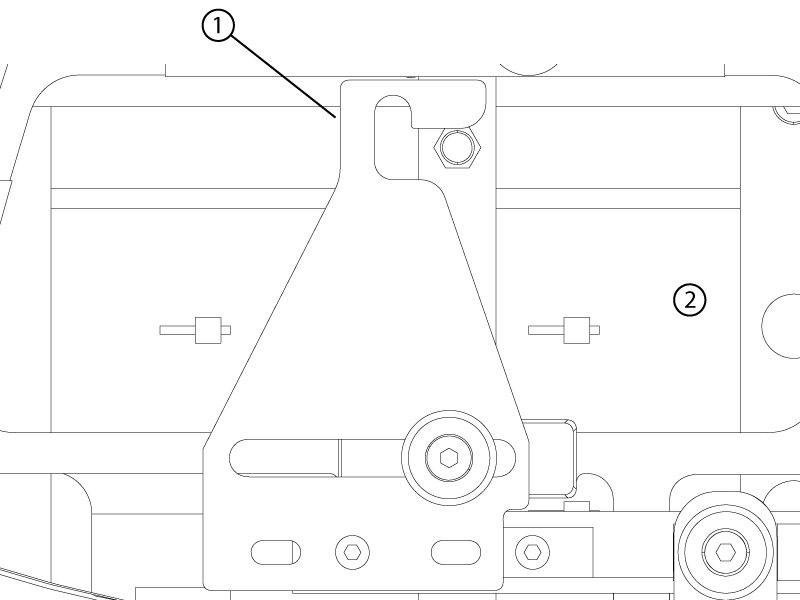
1 Caster pin hook 2 Front of table - Apply Loctite and install the shoulder screw by hand in the assembly order shown below.Note: Forward to rear positioning of the linkage with respect to the screw is not important.
Figure 21. Shoulder screw stackup 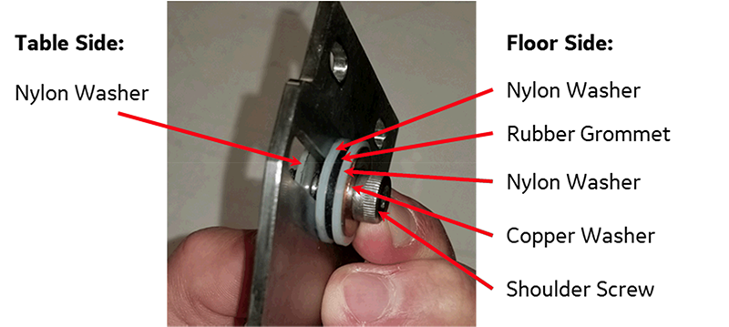
- Apply Loctite and install the shoulder screw by hand in the assembly order shown below.
Front left and right brake link plate replacement
Procedure
- Remove the front plate link by removing the two screws securing it to the shaft linkage.
Figure 22. Front right (closed travel path) brake link plate (view from bottom) 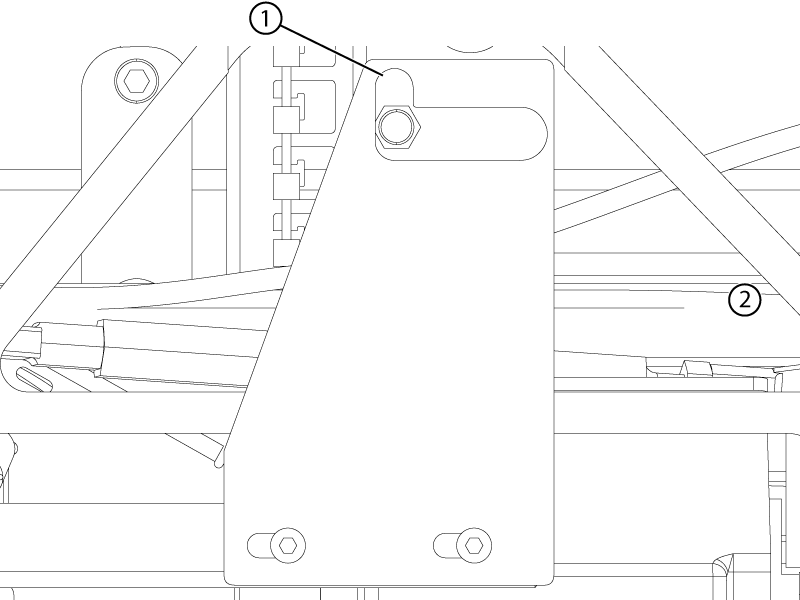
1 Caster pin hook 2 Front of table
Finalization
Procedure
- For all replaced parts, make sure there is sufficient contact area where the caster pin and the brake linkage plate hook engage. Adjust the caster to create contact area if required.
Figure 23. Caster pin engagement 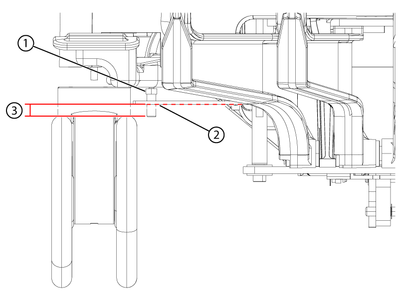
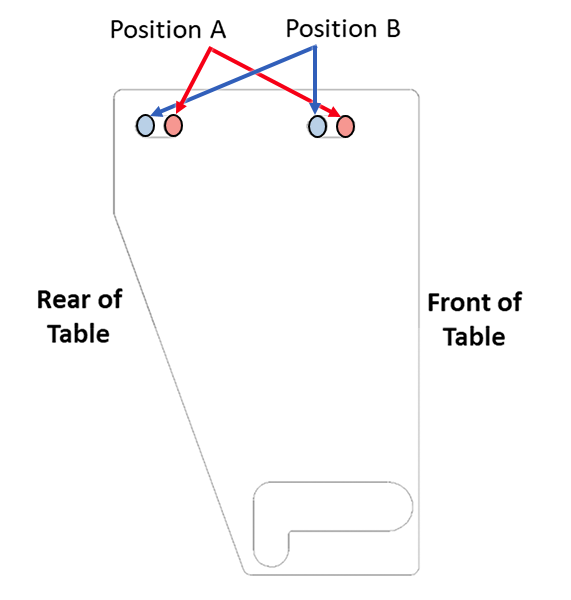
1 Caster pin nut above the link plate 2 The plate may sag. Lightly push the plate down to lowest sag point. 3 Minimum of 2mm below the plate at its lowest point - If a caster fails the finalization test, consider adjusting that associated link from its current position to the opposite position (position A to position B or position B to position A).
Figure 24. Left rear brake link plate (view from top) 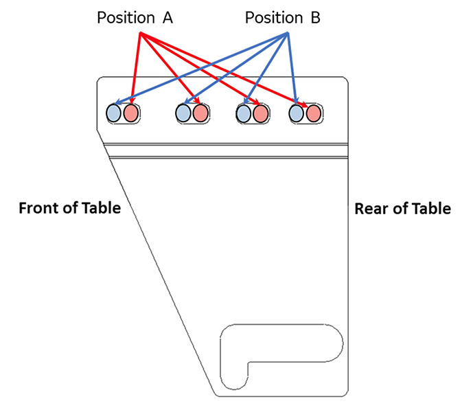
Figure 25. Right rear brake link plate (view from top) 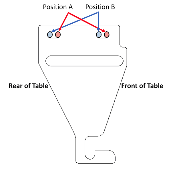
Figure 26. Right front brake link pate (closed travel path) (view from top)