
- Optima MR450w BASE 1.5T System Service Methods
- 5690012-2EN Revision 3
- 00000018WIA3066C030GYZ
- id_123745891.7
- Jan 17, 2020 11:17:00 AM
Arm Board Hinge and Shoulder Screw Replacement
Prerequisites
| Required persons | Preliminary requirements | Procedure | Finalization |
|---|---|---|---|
| 1 | Not Applicable | 90 minutes | Not Applicable |
| Item | Quantity | Effectivity | Part number | Manufacturer |
|---|---|---|---|---|
| Non-Magnetic Service Tool Kit | 1 | - |
5112581 | - |
| Item | Quantity | Effectivity | Part number | Manufacturer |
|---|---|---|---|---|
| Loctite 242 (10 cc) | 1 | - | - | - |
| Item | Quantity | Effectivity | Part number | Manufacturer |
|---|---|---|---|---|
| Right Rear and Left Front Arm Board Hinge | 1 | - |
See FRU Manual. | - |
| Left Rear and Right Front Arm Board Hinge | 1 | - |
See FRU Manual. | - |
| Shoulder Screw, 1/4 in-20 x 1/2. ss 18–8 | 1 | - |
See FRU Manual | - |
Arm Board Hinge Replacement
Procedure
- Move the arm board on the table into the up position by squeezing
the lever on the underside and lifting up. (Shown below.)
Figure 1. Lifting Up Arm Board 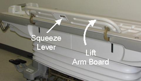
- Using the short tip Allen wrench (to access inner screw), remove
two screws attaching the hinge to the arm board. (Shown below.)
Figure 2. Two Upper Hinge Screws 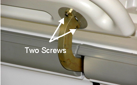
- Using the short tip Allen wrench (to access inner screw), remove
three screws attaching the hinge to the table. (Shown below.)
Figure 3. Three Lower Hinge Screws 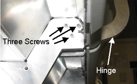
- Using a flathead screwdriver, remove the two screws from the
lever mechanism cover under the arm board. (Shown below.)
Figure 4. Lever Mechanism Screws 
- Loosen the setscrew securing the cable to the lever mechanism
and remove the cable to allow the hinge mechanism to be removed completely.
(Shown below.)
Figure 5. Lever Mechanism Cable 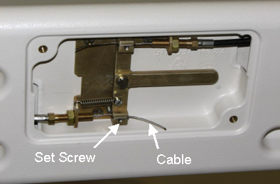
- Reattach the arm board hinge to the table with three lower hinge
screws. (Shown below.)
Figure 6. Three Lower Hinge Screws - After applying a small amount of Loctite 242 to each upper hinge
screw, reattach the arm board hinge to the attaching the arm board
with the two upper hinge screws. (Shown below.)
Figure 7. Two Upper Hinge Screws
Arm Board Stop Shoulder Screw Replacement
Procedure
- Unscrew the Upper Left Rear Cover. This section removal requires
unscrewing the section from both the bellows and the Table. (Shown
below.)
Figure 8. Table Covers 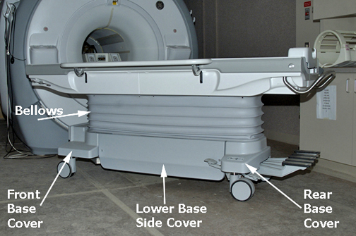
Once unfastened, the Upper Left Rear Cover can be placed out of the way by sliding around handle. (Shown below.)Notice Figure 9. Upper Cover Removal 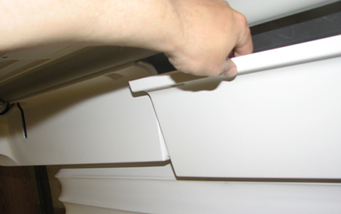
- Locate the bumper shoulder screw and replace as needed. (Shown
below.) Apply Loctite when reinstalling.
Figure 10. Bumper Shoulder Screw 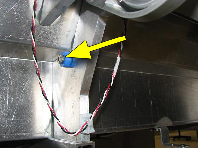
Finalization
Finalization
Dock Table and verify proper operation from Operator Console.