
- Optima MR450w BASE 1.5T System Service Methods
- 5690012-2EN Revision 3
- 00000018WIA30DE1130GYZ
- id_152711042.7
- Jan 17, 2020 10:41:14 AM
Dock Component Replacement
Prerequisites
| Required persons | Preliminary requirements | Procedure | Finalization |
|---|---|---|---|
| 2 | - | 60 minutes for 450/750/450w; 130 minutes for 450w GEM/750w GEM | - |
| Item | Quantity | Effectivity | Part number | Manufacturer |
|---|---|---|---|---|
| Non-Magnetic Tool Kit | 1 | - |
5112581 or 5113258 | - |
| Item | Quantity | Effectivity | Part number | Manufacturer |
|---|---|---|---|---|
| Loctite 242 Threadlocker | (1) 0.5CC Tube | - | - | - |
| Fish Paper | As needed | - | - | - |
| Self-locking Cable Tie | As needed | - |
46-208758P5 | - |
| Item | Quantity | Effectivity | Part number | Manufacturer |
|---|---|---|---|---|
| Dock Motor | 1 | - |
See FRU manual | - |
| SPDT Snap Action Switch | 4 | - |
See FRU manual | - |
| Dock Pedal Spring | 2 | - |
5448742 | - |
| ||||||||||||
| Condition | Reference | Effectivity |
|---|---|---|
|
All persons performing this procedure must complete GE-certified MR safety training. | - | - |
Overview
About this task
This document describes how to perform the following procedures:
-
Dock Cover Removal: Dock Cover Removal
-
Dock Motor Replacement: Dock Motor Replacement
-
Dock Switch Removal and Installation: Dock Switch Removal and Installation
-
Dock Pedal Spring Replacement: Dock Pedal Spring Replacement
-
Dock Cover Reinstallation: Dock Cover Reinstallation
Dock Cover Removal
Procedure
Remove the dock from the magnet room. See Dock Removal and Reinstallation.Warning 
- Remove four bolts (two on each side) to unfasten the dock cover
from the dock base.
Figure 1. Dock Cover and Dock Base 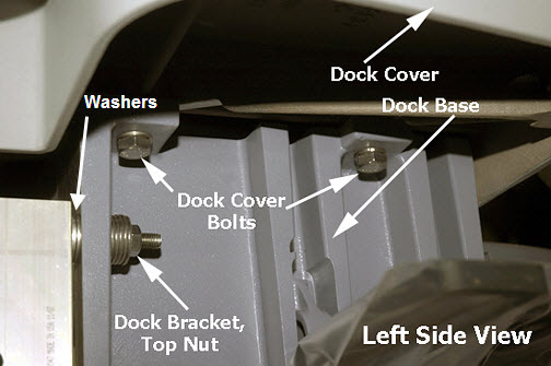
- While removing the dock cover, disconnect the switch connector.
Figure 2. Switch Connector 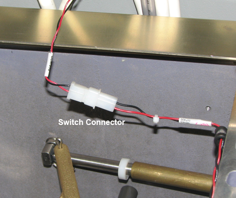
Dock Motor Replacement
Dock Motor Removal
Procedure
Remove the dock from the magnet room. See Dock Removal and Reinstallation.Warning - Disconnect the dock motor power cable, terminal wires, and ground
wire.
Figure 3. Power Cable, Terminal, and Ground Wires 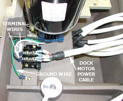
- Remove four screws (two on each side) from the dock motor mount
plate.
Figure 4. Dock Motor Mount Plate Screws 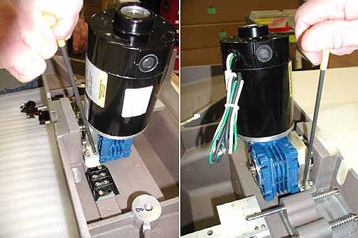
Dock Motor Installation
Procedure
- Remove the e-clip from the end of the dock gearbox shaft on
the old dock motor using the blade of a slotted screwdriver. Secure
the e-clip during removal to prevent the clip from flying away when
pressured.
Figure 5. Old Dock Motor, Gearbox Shaft, and E-Clip 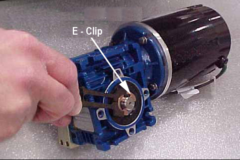
- Slide the dock gearbox shaft and key out of the dock motor and
set it aside. Remove four screws and mounting plate.
Figure 6. Dock Gearbox Shaft 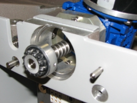
- Apply Loctite 242 on the hex screws of the new motor.
Figure 7. Dock Motor, Mount Plate, and Screws 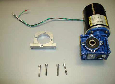
Tie-wrap the cables as shown in Figure 8.Warning Figure 8. Dock Motor Cables Tie-Wrapped 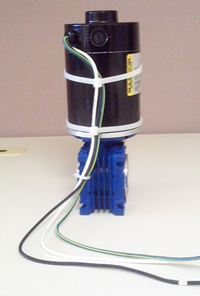
- Reconnect the terminal wires, ground wire, and power cable to
original terminal strips. See Figure 3 and the following
illustration.
Figure 9. Wiring 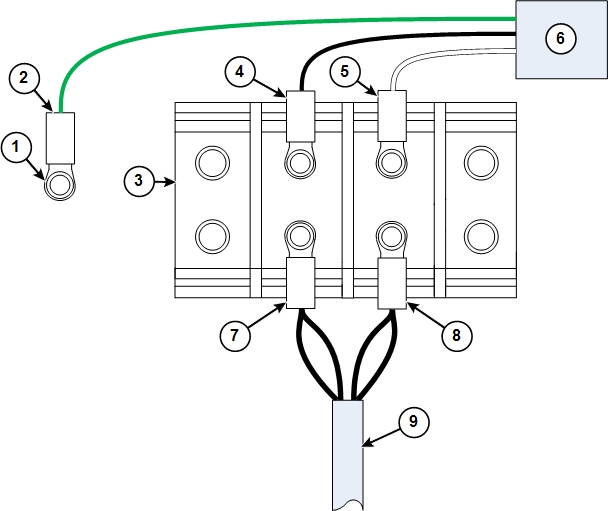
1 Ground stud 6 Dock motor 2 Ground wire from dock motor (green) 7 Dock motor cable connectors for position 1 3 Terminal block 8 Dock motor cable connectors for position 2 4 Black wire from dock motor (black) 9 Dock motor cable 5 White wire from dock motor (white)
Dock Switch Removal and Installation
About this task
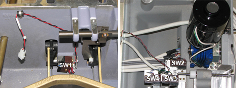
Switch 1 is located in the bottom casting. Switches 2, 3, and 4 are located in the dock cover.
Procedure
Remove the dock from the magnet room. See Dock Removal and Reinstallation.Warning
Dock Pedal Spring Replacement
Procedure
Remove the dock from the magnet room. See Dock Removal and Reinstallation.Warning - Remove both of the old pedal springs from the dock pedals. The
springs are held in place only by spring tension. Pull up on one end
of each spring to remove them from the pedal assemblies.
Figure 11. Dock Pedal Spring Locations 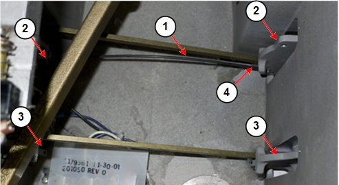
1 Dock pedal spring 3 Dock pedal assembly without spring 2 Dock pedal assembly with spring in place 4 Pull up on spring end to remove spring
Grasp one end of the dock pedal spring. Insert the end of the spring into the hole at the end of one of the dock pedals.Notice Figure 12. Hole for Dock Pedal Spring 
1 Dock pedal assembly 2 Hole for dock pedal spring Figure 13. Inserting Dock Pedal Spring 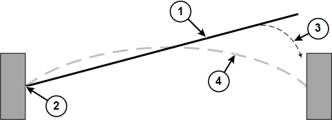
1 Dock pedal spring 2 Grasp one end of the spring and insert it into the hole at the end of one dock pedal. 3 Grasp the end of the spring approximately 1 inch (25 mm) from the end of the spring, and then gently insert the end into the hole in the other dock pedal. 4 Position of the dock pedal spring after installation - Grasp the other end of the dock pedal spring (at approximately
1 inch (25 mm) from the free end of the spring), and gently insert
it into the hole at the end of the other dock pedal. It is easier
to insert the spring into the pedal if you press down on the pedal.
Figure 14. Dock Pedal Spring Grasp Point 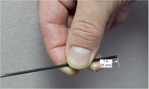
Dock Cover Reinstallation
Procedure
- Reattach the switch connector. See Figure 2.
- Place the dock cover onto the dock base and reattach the dock cover bolts. See Figure 1.
- Reinstall the dock. See Dock Removal and Reinstallation.
Finalization
Finalization
-
Perform Dock Adjustments and Dock Hardware Adjustments as necessary.
-
Ensure the motor is functioning properly when docking the patient table and verify that lowering the table results in automatic retraction of the LPCA into the bridge.