
- Optima MR450w BASE 1.5T System Service Methods
- 5690012-2EN Revision 3
- 00000018WIA303AF030GYZ
- id_123738881.16
- Sep 2, 2020 2:33:10 PM
PAC and SRI-4 Replacement
Prerequisites
| Required persons | Preliminary requirements | Procedure | Finalization |
|---|---|---|---|
| 1 | Not Applicable | 30 mins. for PAC; 45 mins. for SRI | 30 minutes |
| Item | Quantity | Effectivity | Part number | Manufacturer |
|---|---|---|---|---|
| Nonmagnetic service tool kit | 1 | - |
5112581 | - |
| Item | Quantity | Effectivity | Part number | Manufacturer |
|---|---|---|---|---|
| PAC-2BV FRU | 1 | - | - | - |
| PAC-2B FRU | 1 | - | - | - |
| PAC-5 FRU | 1 | - | - | - |
| ||||
About this task
Overview
This procedure explains replacement of the physiological acquisition controller (PAC) assembly and the scan room interface (SRI-4) on a fixed site system.
The systems may have either a PAC-2B, a PAC-2BV, or a PAC-5. The PAC-5 is backward compatible with the PAC-2B/PAC-2BV. There is no impact with PAC hardware configuration in Guided Install.
Removal of the PAC
Procedure
- The PAC is under the left side of the magnet enclosure, near the top of the magnet.
Figure 1. PAC and SRI Location 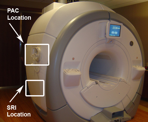
- Disconnect all cables from the I/O panel except the white PPG cable, which is permanently attached.
- Carefully remove and slide the cover around the PPG cable. Avoid damage to the cable while removing the cover.
Figure 2. PAC and SRI Exposed 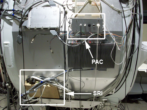
- Carefully remove and slide the cover around the PPG cable. Avoid damage to the cable while removing the cover.
Installation of the New PAC
Procedure
- Check the alignment of the PAC with the enclosure in all three
planes.
-
There are adjustment screws that allow for adjustment up/down, left/right, and in/out.
-
Adjust the PAC I/O panel so that it lines up with the slot in the enclosure in the left/right and up/down plane, and adjust it in/out so the gap between the I/O panel and the enclosure is less than 1 mm.
Figure 3. PAC Alignment (RRx Systems) 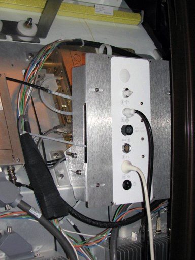
-
Removal of the SRI
Procedure
- Disconnect the cables attached to the SRI.
Figure 4. SRI Cable Map 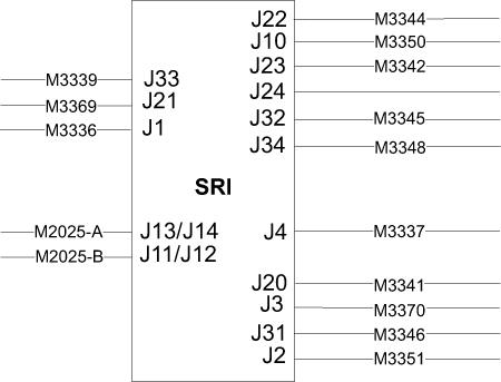
Installation of the New SRI
Procedure
- Place the new SRI in the proper location, and install in the reverse order of how it was removed.
- Mount the removed temperature sensor box on the replacement SRI.
- Reconnect the cables and replace the enclosure panels.
- Remove LOTO and restore power to the system. See the MR Service Safety Manual, PN 5452735.
Finalization
Procedure
- Perform a TPS reset.
- Confirm that the reported problem has been resolved by running PAC or SRI diagnostics. In Service Methods, instructions for these diagnostics can be found in Troubleshooting > Diagnostics > Hardware Location > Magnet Room > PAC Diagnostic Tests and SRI Functional Diagnostics.
- Perform a Check Scan.