
- Optima MR450w BASE 1.5T System Service Methods
- 5690012-2EN Revision 3
- 00000018WIA303FC030GYZ
- id_123749351.10
- Jan 17, 2020 11:28:39 AM
Bore Light Replacement
Prerequisites
| Required persons | Preliminary requirements | Procedure | Finalization |
|---|---|---|---|
| 1 | Not Applicable | 10 mins. for rear bore lights, 90 mins. for front bore lights (450w); 10 mins. for rear or front (450w GEM or 750w GEM) | Not Applicable |
| Item | Quantity | Effectivity | Part number | Manufacturer |
|---|---|---|---|---|
| Non-Magnetic Service Tool Kit | 1 | - |
5112581 | - |
| Item | Quantity | Effectivity | Part number | Manufacturer |
|---|---|---|---|---|
| Front Bore Light Assembly | 1 | - |
See FRU Manual | - |
| Rear Bore Light Left Assembly | 1 | - |
See FRU Manual | - |
| Rear Bore Light Right Assembly | 1 | - |
See FRU Manual | - |
About this task
Overview
Use this procedure to replace the front and rear bore lights.
Preliminary Steps
Procedure
- Perform LOTO on the PDU. See the MR Service Safety Manual, PN 5452735.
- Move the patient table away from the magnet.
Front Bore Light Replacement
Procedure
- Remove the two attachment screws.
Figure 1. Front Bore Light Assembly 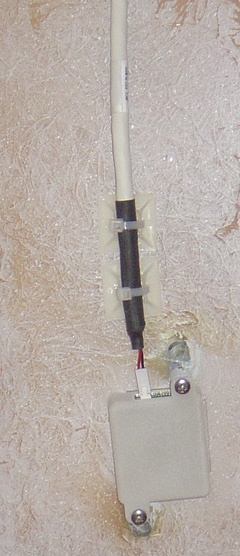
Rear Bore Light Replacement
Procedure
- Gently slide the bore light assembly down the inside wall of
the rear end bell (this disconnects the bore light assembly from the
cable).
Figure 2. Rear Bore Light Assembly 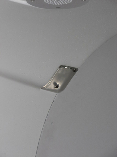
Finalization
Finalization
-
Remove LOTO from the PDU. See the MR Service Safety Manual, PN 5452735.
-
Press the bore light button on the operator control panel to test the bore lights.