
- Optima MR450w BASE 1.5T System Service Methods
- 5690012-2EN Revision 3
- 00000018WIA3057F030GYZ
- id_123738831.14
- Sep 11, 2020 10:16:59 AM
LPCA Quick Disconnect Module Replacement
Prerequisites
| Required persons | Preliminary requirements | Procedure | Finalization |
|---|---|---|---|
| 1 | Not Applicable | 10 minutes | 30 minutes |
| Item | Quantity | Effectivity | Part number | Manufacturer |
|---|---|---|---|---|
| Non-magnetic service tool kit | 1 | - |
5112581 or 5113258 | - |
| Item | Quantity | Effectivity | Part number | Manufacturer |
|---|---|---|---|---|
| Quick disconnect assembly | 1 | - |
See FRU manual | - |
| ||||
About this task
Overview
The LPCA quick release module is also referred to as the quick disconnect assembly, emergency release module, or quick disconnect connector. The LPCA quick disconnect modules allow for easy replacement of the coil connectors as they slide on and off their own track with minimal effort.
MR450, MR450w, MR750, and MR750w have both P1 and P2 coil connectors on the LPCA.
Procedure
- Grasp the quick disconnect module and pull and slide forward
as shown below to remove it from plastic guide track and fixed rear
connector assembly.
Figure 2. Quick Disconnect Module Removal Path 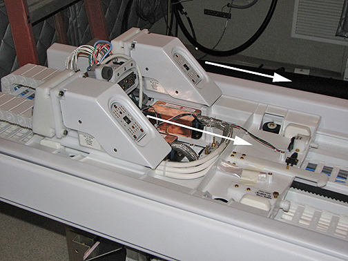
- Re-dock the patient table to drive the LPCA to the home position
and reattach to the cradle/patient table. Dock the table by pressing
the mechanical docking pedal. For tables equipped with P-connectors
or GEM coil, next engage the electrical dock connector by pressing
the middle foot pedal.
Figure 3. Electronic Docking Pedal 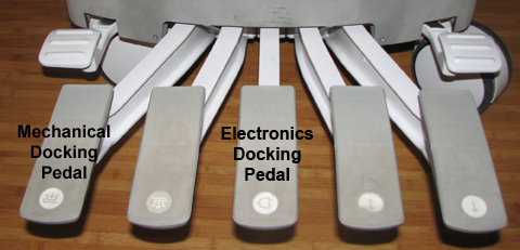
Finalization
-
Plug in all customer P-port connector coils into the new quick disconnect connectors. Lock the connectors to ensure the correct mating of the parts. Be aware that connector spindle receptacles require periodic lubrication as part of PM process. If the P-port does not lock, the spindle on the coil receptacle may need replacing. See ODU Connectors Cleaning and Replacement.
-
Perform a head or body scan. Scan faults can result from poorly seated quick disconnect modules.