To prevent fatal electric shock, disconnect power from the PDU before you perform any procedure that requires you to remove the dock.
PERFORM LOCKOUT/TAGOUT PROCEDURE. See the MR Service Safety Manual, PN 5452735.
Warning
POSSIBLE PERSONAL INJURY!
THIS PROCEDURE REQUIRES MOVEMENT OF FERROUS MATERIAL IN CLOSE PROXIMITY TO THE MAGNET.
TWO FIELD ENGINEERS ARE REQUIRED AT ALL TIMES.
Warning
Personal injury and equipment damage
Strong Magnetic Field
When servicing any magnetic equipment, it is critically important that the service engineer consciously plan the path to be taken when moving highly ferrous devices in the magnet environment. the path should be as far from the magnet as practical and avoid high flux-density fields.
Safety Requirements
The service path must allow for the dock to be moved along the ground a distance equal to that of the distance between the magnet and the foot-end of the patient table prior to being lifted vertically.
Two (2) MR safety trained personnel must be present at all times when servicing highly ferrous devices in the areas of magnetic fields.
When planning a service path, it is critical that the path be clear and sufficiently wide. Ensure that there are no trip hazards, obstacles, clutter, slippery surfaces or other items even partially restricting the path. If there are portable obstacles in a path, remove them from the area and replace them after the service action is completed. It is required to walk the path prior to beginning service to ensure that there is sufficient space through which to pass for yourself and the object being serviced.
About this task
This dock adjustment procedure is required to properly align the cradle to the bridge in both the Z and X directions. Proper dock alignment ensures smooth travel of the cradle and protects table components from premature wear.
Dock centering
About this task
This procedure describes the longitudinal adjustment (in and out) and the lateral adjustment (left to right) to center the dock. For proper patient table docking, the dock assembly must be adjusted to meet these criteria:
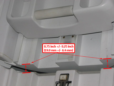
The gap between the leading edge of the cradle top and the front of the bridge must be 0.75 inch ±0.25 inch (19.0 mm ±6.4 mm). This ensures that the gap is narrow enough to allow for smooth travel, but large enough to avoid rubbing on covers or bridge and to avoid pinch hazard. See Figure 1.
The dock assembly must be square to the bridge, so the axis of the cradle travel is the same for both the patient table and bridge.
The bosses of the dock and the patient table must align to ensure proper rotary pump alignment.
Longitudinal adjustment
Procedure
With the patient table docked, measure the distance from the patient table top to the front of the magnet bridge. The distance should be 0.75 inch ±0.25 inch (19.0 mm ±6.4 mm). Also, the distance from the patient table top to the front of the magnet bridge should be equal so the patient table top is colinear with the bridge.
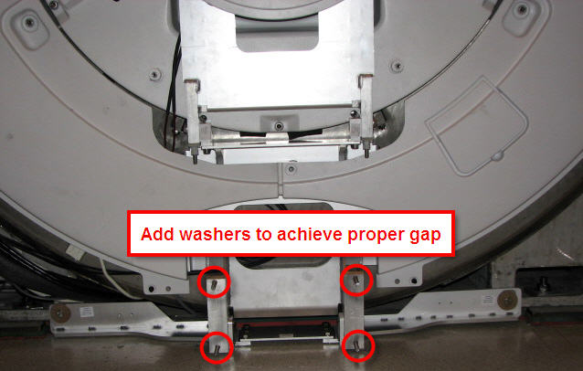
Add or remove washers at the dock assembly and measure until the proper gap is achieved.
Figure 2. Dock positioning adjustment
Lateral adjustment
Procedure
Raise the table to maximum height using the UP foot pedal.
Dock the patient table.
Drive the cradle all the way into the bore. Do the dock lateral adjustment until the vertical wheel tracks are aligned right and left.
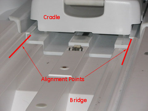
Check the alignment of the patient table against the bridge (left-to-right alignment only). Use the vertical wheel tracks to line up the table with the magnet bridge. Use the inner edge corners of the table and magnet bridge as alignment points. Height is adjusted using the Table Top Height Adjustment procedure.
Figure 3. Cable track alignment points
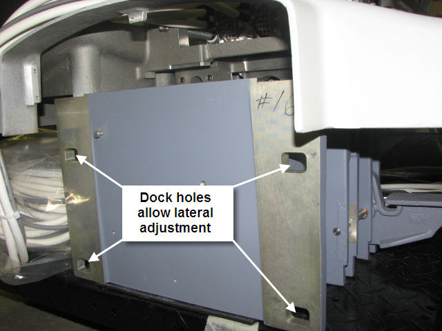
If adjustment is required, loosen the nuts on the dock bracket (shown in Figure 2) to the rear of the dock (shown in Figure 4). Move the dock left or right to the proper position so the wheel tracks line up.
Figure 4. Rear of dock and lateral bolt holes
Boss alignment
About this task
The goal for the boss alignment is to have the center of each boss be the same between the dock and the table. This alignment ensures that the rotary pump and the dock connector are properly aligned.
Procedure
Dock the patient table.
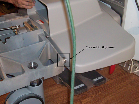
Inspect the bosses on both sides of the table and dock for concentric alignment.
Figure 5. Inspect bosses for concentric alignment
Note: A missing front table cover, as shown in Figure 5 may result in 16-channel systems reporting a 32-channel electrical connector not attached. When adjustment is complete, replace the front cover to prevent these errors.
Adjust the table casters as necessary to ensure concentric alignment in the vertical direction. The final distance between the dock boss and the table boss should be ±1.0 mm. (See Leveling Patient Table.)
Dock hook tension adjustment
Procedure
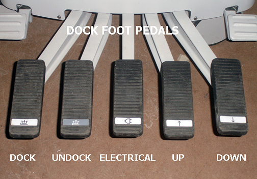
Dock the patient table using the DOCK pedal, paying close attention to the force required to engage the docking mechanism. (Initial docking should not require significant force to depress the dock pedal.)
Figure 6. Foot Pedals
Note the following dock pedal conditions:
When depressing the dock pedal, if the force needed was other than a crisp snap at the bottom of the pedal stroke, then one of two conditions are in effect and action is required:
Too loose - Minimal or no force at all was needed to reach the bottom of the stroke.
Too tight - Considerable to significant force was needed to reach the bottom of the stroke, resulting in a hard, strong snap at the end.
Note: Both conditions (too loose and too tight) require the same action of loosening the set screw.
CAUTION
Equipment damage!
The hook can become overstressed and bend, requiring replacement.
Do not attempt to fully engage the dock pedal if the force needed is too strong.
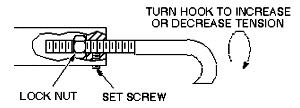
Count the number of turns made in this step. Tightening (turning the hook clockwise) is a positive number; loosening (turning the hook counterclockwise) is a negative number.
Adjust the hook by loosening the lock nut at the rear of the hook, and turning the hook clockwise (to tighten) or counterclockwise (to loosen). One full turn is equal to 1/16 inch.
Note: The patient table must be undocked for all hook adjustments. Make the appropriate number of turns on the hook, retighten the lock nut, and then retest the force needed on the dock pedal when docking the table.
Figure 7. Dock hook tension adjustment
Repeat Step 4 until a crisp snap of the hook is achieved when docking the patient table.
Re-tighten the set screw.
Finalization
Finalization
Replace all covers.
Dock the table.
Confirm that the cradle release functions properly.
Confirm that the LPCA connects to the cradle and that the cradle can move into the bore.

 Note: A missing front table cover, as shown in Figure 5 may result in 16-channel systems reporting a 32-channel electrical connector not attached. When adjustment is complete, replace the front cover to prevent these errors.