
- Optima MR450w BASE 1.5T System Service Methods
- 5690012-2EN Revision 3
- 00000018WIA3069AE20GYZ
- id_131058353.5
- Feb 6, 2020 1:42:26 PM
Front end bell removal and installation
Prerequisites
| Required persons | Preliminary requirements | Procedure | Finalization |
|---|---|---|---|
| 2 | Not Applicable | 1.5 hours | Not Applicable |
| Item | Quantity | Effectivity | Part number | Manufacturer |
|---|---|---|---|---|
| Nonmagnetic Titanium Service Tool Kit, Large Set | - | - | 5112581 | - |
| Item | Quantity | Effectivity | Part number | Manufacturer |
|---|---|---|---|---|
| Front End Bell Assembly | 1 | - |
See FRU Manual | - |
| ||||
Procedure
- Remove the bridge assembly. See Bridge and Longitudinal Drive Belt Replacement.
Figure 1. Front end bell 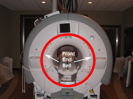
- On the 7-segment display (7SD) version, remove the trim ring pieces and front bezel, as follows:
- Remove the front bezel screw and pop off the bezel.
Figure 2. Remove front bezel screw 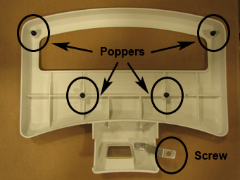
- Remove the front bezel screw and pop off the bezel.
- On the IRD version, follow these steps:
- Remove the trim rings.
Figure 3. Remove trim rings 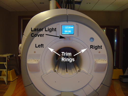
- Remove the trim rings.
- Remove the L-brackets from the vibration bracket.
Figure 4. L-Bracket removal 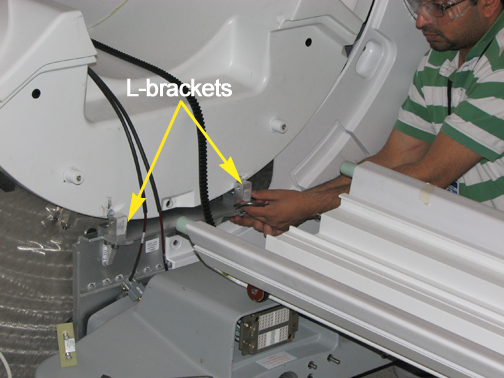
- Remove the screws holding the front end bell to the arm brackets.
Figure 5. Front end bell screws 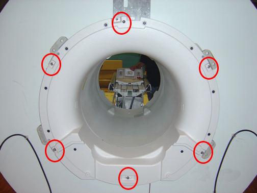
- Reverse the steps to install the replacement front end bell. Confirm the gap between the front end bell and the RF body coil is 2.5 +/- 0.5 mm with a desired gap of 2.0 mm. Verify the proper fit of the covers.If the gap measurement is outside the desired range, see RF Body Coil Replacement.
Guide studs, located in the Service Cable Hardware Kit, may be screwed into the top two M10 bolt sockets to assist placing the replacement front end bell.
Figure 6. Guide Stud 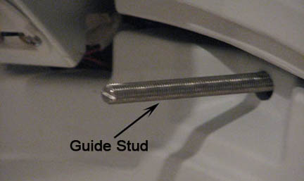
Finalization
- Remove LOTO from the PDU. See the MR Service Safety Manual, PN 5452735.
- Ensure the microphone and bore lights work.
- Complete a body scan (see Doing a check scan).