
- Optima MR450w BASE 1.5T System Service Methods
- 5690012-2EN Revision 3
- 00000018WIA30B31130GYZ
- id_123749301.1
- Jul 5, 2019 10:03:32 PM
Table Interface Module Replacement
Prerequisites
| Required persons | Preliminary requirements | Procedure | Finalization |
|---|---|---|---|
| 1 | Not Applicable | 30 minutes | 10 minutes |
| Item | Quantity | Effectivity | Part number | Manufacturer |
|---|---|---|---|---|
| Non-Ferrous Tool Kit | 1 | - |
5112581 | - |
| Item | Quantity | Effectivity | Part number | Manufacturer |
|---|---|---|---|---|
| Table Interface Module (TIM) | 1 | - |
5176474 | - |
| ||||
About this task
Overview
This procedure describes the replacement of the table interface module.
Procedure
- Disconnect the cables attached to the TIM.
Figure 1. Location of TIM 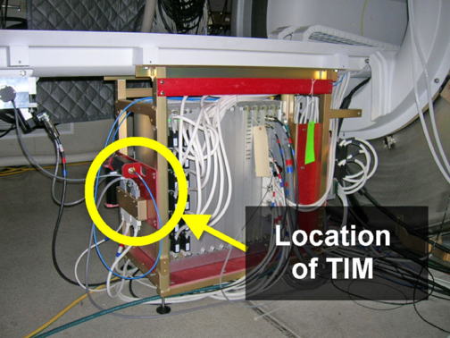
Figure 2. Close-Up of TIM 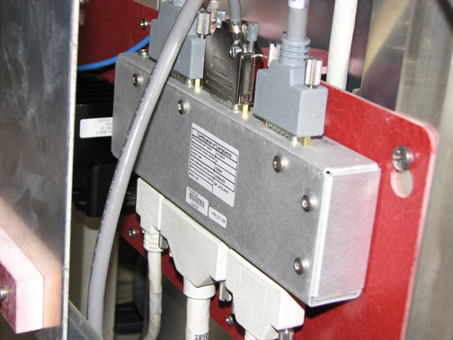
Finalization
Remove LOTO. See the MR Service Safety Manual, PN 5452735.