
- Discovery MR750 3.0T System Service Methods
- 5690009-2EN Revision 4
- 00000018WIA300DBE20GYZ
- id_131075373.1
- Nov 27, 2019 10:21:33 AM
Gradient and RF Body Coil Air Flow Sensor Replacement
Prerequisites
| Required persons | Preliminary requirements | Procedure | Finalization |
|---|---|---|---|
| 2 | Not Applicable | 120 minutes | 45 minutes |
| Item | Quantity | Effectivity | Part number | Manufacturer |
|---|---|---|---|---|
| Non-Magnetic Service Tool Kit | 1 | - |
5112581 | - |
| Item | Quantity | Effectivity | Part number | Manufacturer |
|---|---|---|---|---|
| Air Flow Sensor | 1 | - |
FRU number depends on system type. See Field Replaceable Units (FRUs). | - |
About this task
This procedure describes the replacement of the gradient and RF body coil air flow sensor.
Procedure
- Disconnect the RF body coil air flow sensor housing from the
scan room interface (SRI).
Figure 1. Air Flow Sensor Housing with Connector 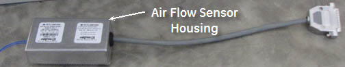 Note:
Note:The illustration below is for reference only; sensor head housings are not shown.
Figure 2. Air Flow Sensor Assembly Drawing 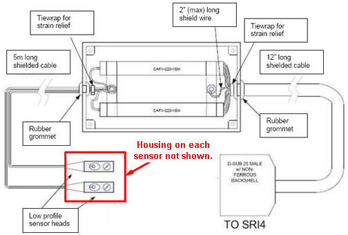
- Locate the RF coil air flow sensor head housings at approximately
the 11 o'clock and 1 o'clock positions on the magnet enclosure.
Figure 3. RF Coil Air Flow Sensor Head Housings 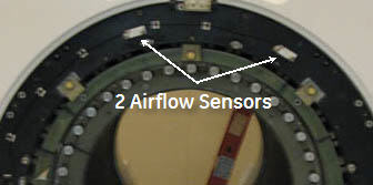
- Remove and save the two screws securing each sensor head housing
to the magnet enclosure.
Figure 4. Removal of Air Flow Sensor Head Housings 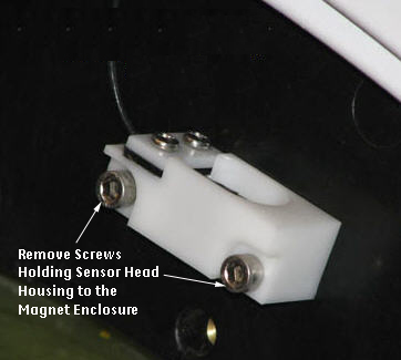
Finalization
- Ensure that sensors are operating correctly. See Body Air Flow Functional Check.
- Ensure the laser light is aligned. See Laser Light Alignment.