- Discovery MR750 3.0T System Service Methods
- 5690009-2EN Revision 4
- 00000018WIA30AFD030GYZ
- id_123749311.5
- Feb 3, 2022 2:30:26 PM
Gradient Filter Replacement
Prerequisites
| Personnel requirements | |||
|---|---|---|---|
| Required persons | Preliminary requirements | Procedure | Finalization |
| 1 | Not Applicable | 30 minutes | Not Applicable |
| Tools and test equipment | ||||
|---|---|---|---|---|
| Item | Quantity | Effectivity | Part number | Manufacturer |
| Digital volt meter (DVM) with alligator clip leads | 1 | - | - | - |
| Non-ferrous tool kit | 1 | - |
| - |
| Replacement parts | ||||
|---|---|---|---|---|
| Item | Quantity | Effectivity | Part number | Manufacturer |
| Gen1 Gradient Filter Assembly (RoHS) | 1 | - | 5166619-50 | - |
| ||||||||
About this task
Overview
The gradient filter attaches to the secondary pen wall (SPW) from the equipment room. The thumbscrews on the filter attach to PEM nuts on the SPW.
Removing GEN1 Gradient Filter
Procedure
Perform LOTO on the PGR cabinet. Refer to the Applying LOTO - ISC procedure.DANGER 
From the scan room side of the gradient filter, remove the plastic gradient filter terminal covers.Warning 
Figure 1. Gradient Filter Assembly Gen1 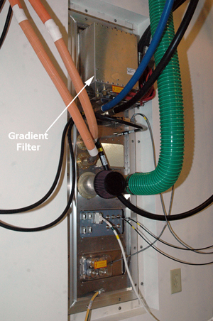 Note:
Note:Two wrench technique: Use two wrenches when removing the cables from the gradient input/output connectors on each side of the SPW. One wrench prevents the post from turning, while the other loosens the nut. If you try to loosen the nut with only one wrench, the post itself could turn and damage the gradient filter.
- While in the equipment room at the SPW, remove the screws securing
the gradient filter assembly to the SPW panel.
Remove the gradient filter and set aside.
Figure 2. Gradient Filter Thumbscrews 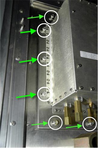
Installing GEN1 Gradient Filter
Procedure
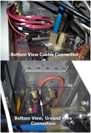
- Attach the cables to the gradient filter connections on both sides of the filter. Start with the GND, Z-axis, Y-axis, and X-axis cables and ground wires. Snugly tighten each cap nut to attach the correct axis cable to the correct gradient filter connection. The lug connections between axis and polarities should not be touching.
Figure 3. Gradient Terminals 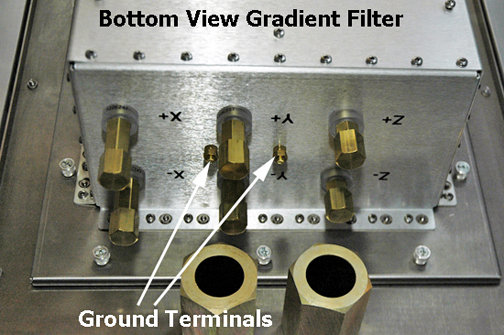 Note:
Note:Red cable indicates positive (+) wires, black cables indicate negative (-) wires.
Two wrench technique: Use two wrenches when attaching the cables from the gradient input/output connectors on each side of the SPW. One wrench prevents the post from turning, while the other tightens the nut. If you try to tighten the nut with only one wrench, the post itself could turn and damage the gradient filter.
Note:Make sure to tighten each cable as you attach it, because you cannot reach all cables after attaching them.
- Tighten the cap nuts and verify that nuts are not loose.
Verify that all connections are tight, correct, and not touching each other. Make sure each screw is fixed, each nut is tight, and each cable is not detached from terminal.
Figure 4. Cables Connected