
- Discovery MR750 3.0T System Service Methods
- 5690009-2EN Revision 4
- 00000018WIA30BCBE20GYZ
- id_131064943.4
- Oct 11, 2021 6:13:21 PM
Body coil air flow functional check
Prerequisites
| Required persons | Preliminary requirements | Procedure | Finalization |
|---|---|---|---|
| 1 | Not Applicable | 10 to 15 minutes | Not Applicable |
| ||||
| Condition | Reference | Effectivity |
|---|---|---|
|
System software must be booted. | - | - |
About this task
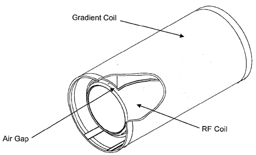
This test checks the functionality of the body coil air blower system, which cools the patient bore wall surfaces by forcing air between the gradient coil and the RF coil Figure 1. Air enters the magnet through two rear air ports; therefore, the rear of the magnet needs to have an airtight seal in order to maintain a sufficient pressure head to force air to flow. This helps to transfer heat away from the bore wall with convection. If there is not an air tight seal in the rear of the magnet, there will not be enough pressure to force air through the space between the gradient and RF coils.
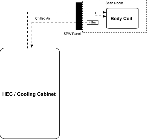
The block diagram below shows the system configuration. Air is pulled out of the magnet room, and travels through the penetration wall and into the heat exchange cabinet (HEC). This air is then cooled and sent back through the penetration wall and into the magnet room. This cooled air then travels from the penetration wall, splits into two air hoses, and into the back of the magnet through tubing in the rear end bell or through tubing in the body coil. At the front of the magnet are two air sensors that capture an average airflow measurement and relay the information back to the HEC display. This airflow requires a measurement of greater than 500 feet per minute (fpm) during scanning operations. If the airflow measurement is less than 500 fpm, see Troubleshooting body coil air flow.
Checking body coil air flow
About this task
This procedure consists of taking readings from the HEC display on the heat exchanger cabinet and determining if an error is occurring with the air flow system.
Procedure
- Go to the heat exchanger cabinet and view the display.
- Select the following buttons from the main menu display in order
to view the airflow set point and feedback readings:
- Note: Select ESC multiple times to return to the main menu display.Monitor (F3)
- Blower (F4)
- Confirm that the airflow set point corresponds to a measurement equal to or greater than 550 fpm.
- Confirm that the air flow feedback corresponds to a measurement
greater than 500 fpm.
- If the feedback is lower than 500 fpm, see Troubleshooting body coil air flow to troubleshoot the body coil air flow.
- If the feedback is greater than or equal to the Normal mode set point, the system is functioning properly.
Troubleshooting body coil air flow
About this task
Procedure
- Check that both air flow sensors are functioning by running the SRI Real-Time Data test. The results of this test include information about the air flow sensors. Scroll down the Test Results window to find the results for Air Flow Sensor 0 and Air Flow Sensor 1.
Figure 3. Air flow sensor readings from SRI real-time data test 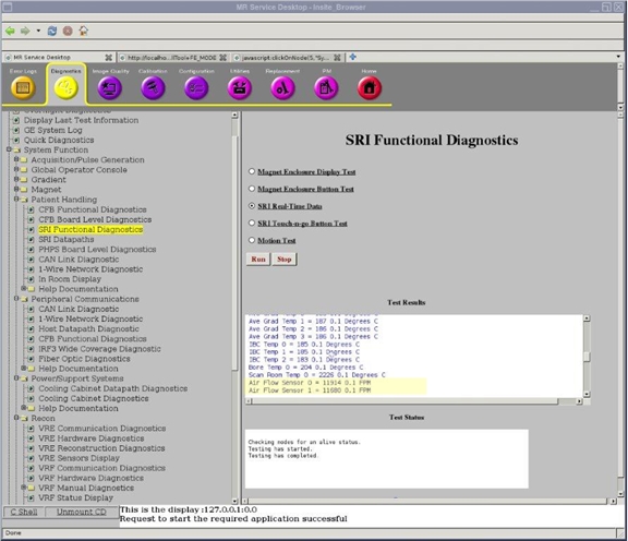
Compare the readings for Air Flow Sensor 0 and Air Flow Sensor 1. These two sensors measure the same air flow. If the readings vary from each other by more than a few percent, there is most likely a problem with one of the air flow sensors or one of the sensors is blocked. See Gradient and RF Body Coil Air Flow Sensor Replacement for information about accessing and replacing the air flow sensors.
The results of the SRI Real-Time Data test also show an additional set of data for the air flow sensors: Air Flow 0 and Air Flow 1. The data is somewhat different because the measurements are performed at different times, but either set of data indicates whether the air flow sensors are operating. (Air Flow 0 and Air Flow 1 also show the voltage of the temperature sensor.)
The air flow must always be greater than 500 fpm. In situations where the air flow falls under 500 fpm, follow the remaining steps in this section. After each step, refer to the HEC control panel to see if the air flow is 500 fpm or greater.
If the air flow is between 450 fpm and 500 fpm, the system can complete a scan, but cannot initiate a scan. If the air flow falls under 450 fpm, the scan control system automatically shuts down.
- Ensure that the farthest right blower variable frequency drive (VFD) display is reading 70.0 Hz.
Figure 4. VFD blower display in HEC 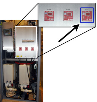
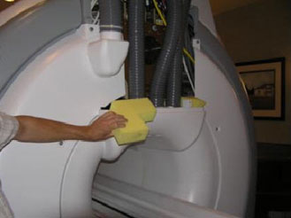
- Ensure that the patient air hose is not swapped with the RF
cooling air hoses. If the patient air hose is not in the appropriate
location, switch it with the RF cooling air hose.
Figure 5. Air flow hoses 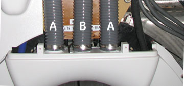
A RF cooling air hose B Patient air hose To distinguish the patient air hose from the RF cooling air hose, use the front control panel to turn off the patient air hose. After the fan is off for patient air flow, there is air flow only through the RF cooling hoses.
- For a system with an in-room display (IRD), press the fan button until the lights to the left are off.
Figure 6. IRD control panel 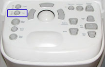
- For a system without an IRD, press the fan button off.
Figure 7. Control panel (no IRD) 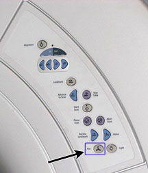
- For a system with an in-room display (IRD), press the fan button until the lights to the left are off.
- Check for any gaps between the rear end bell and the RF body
coil, as well as between the front end bell and the RF body coil.
The gaps between the end bells and the RF body coil should be 2.5 mm ± 0.5 mm.
If an end bell gap is incorrect, see Front End Bell Removal and Installation or Rear End Bell Removal and Installation to correct the gap.
If you see any further leakage of air flow after the end bell re-installation, apply duct tape between the end bell and the body coil interface to avoid the leakage.Figure 8. End bell gap 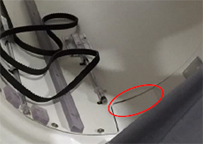
- Check the air seals on the rear end bell. Ensure that the seals
(part numbers 5323651 and 5323652) are in place.
Figure 9. Rear end bell seals 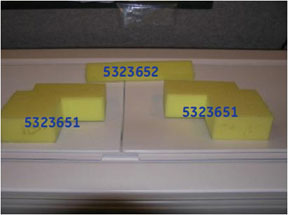
- Remove the front end bell and complete the steps below.
- Check the front orientation of the sensor. Verify that the sensor head is in the center of the cutout and that the bolt heads are facing you.
Figure 10. Front end bell sensors 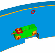
- Check where the cables are routed. Verify that none of the cables are routed on top of the sensors. If there are cables touching the tops of sensors, relocate the cables so they do not disturb the sensors.
Figure 11. Sensor locations 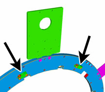
- Check the front orientation of the sensor. Verify that the sensor head is in the center of the cutout and that the bolt heads are facing you.
- Remove the rear end bell and perform the steps below.
- Check the seal between the rear end bell and the XRMB gradient coil. Verify that the seal is not torn or damaged, and that the seal is completely touching the rear end bell.
Figure 12. Seal for rear end bell and XRMB gradient coil 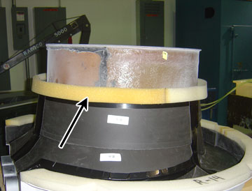
- Check the seal in the gradient coil.
Figure 13. Seal in gradient coil 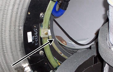
- Check the gap between the RF coil and the gradient coil. Ensure that nothing is stuck in between them.
- Check the seal between the rear end bell and the XRMB gradient coil. Verify that the seal is not torn or damaged, and that the seal is completely touching the rear end bell.
Finalization
Finalization
No finalization steps.