
- Discovery MR750 3.0T System Service Methods
- 5690009-2EN Revision 4
- 00000018WIA30EAAE20GYZ
- id_131058343.4
- Feb 6, 2020 1:49:29 PM
Rear end bell removal and installation
Prerequisites
| Required persons | Preliminary requirements | Procedure | Finalization |
|---|---|---|---|
| 2 | Not Applicable | 135 minutes | 15 minutes |
| Item | Quantity | Effectivity | Part number | Manufacturer |
|---|---|---|---|---|
| Nonmagnetic Titanium Service Tool Kit, Large Set | 1 | - | 5112581 | - |
| Item | Quantity | Effectivity | Part number | Manufacturer |
|---|---|---|---|---|
| Rear End Bell Assembly | 1 | - |
Refer to the FRU Manual | - |
| ||||
Procedure
- Remove the nuts and washers holding the rear pedestal to the
magnet, and move the rear pedestal away from the magnet.
Figure 1. Remove nuts securing pedestal to magnet enclosure 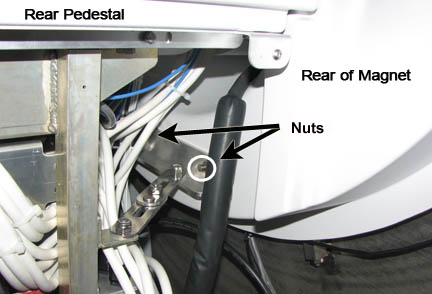
Remove the five screws holding the rear end bell to the turtle bracket.CAUTION Figure 2. Rear end bell screws 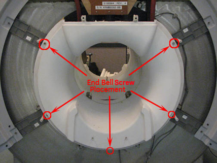
Remove the two RF transmit cables from the RF body coil.Notice 
Finalization
- Remove LOTO from the PDU. See the MR Service Safety Manual, PN 5452735.
- Verify that the speaker, patient air, and bore lights work.
- Do a body scan to ensure the system is working properly (see Doing a check scan).