
- Discovery MR750 3.0T System Service Methods
- 5690009-2EN Revision 4
- 00000018WIA30F8D030GYZ
- id_123739401.14
- Oct 11, 2021 3:47:42 PM
DTRSW and Preamp Combiner Replacement
Prerequisites
| Required persons | Preliminary requirements | Procedure | Finalization |
|---|---|---|---|
| 1 | Not Applicable | 30 minutes | 30 minutes |
| Item | Quantity | Effectivity | Part number | Manufacturer |
|---|---|---|---|---|
| Non-magnetic Phillips Screwdriver | 1 | - | - | - |
| Basic Hand Tool Set | 1 | - | - | - |
| Item | Quantity | Effectivity | Part number | Manufacturer |
|---|---|---|---|---|
| Dual Drive Transmit Receive Switch | 1 | - |
See FRU Manual | - |
| Preamp Combiner | 1 | - |
See FRU Manual | - |
| ||||||||
About this task
Overview
This procedure applies to MR750 systems with a dual drive RF amplifier. For MR750 systems with a single drive RF amplifier, refer to Body Hybrid Replacement .
This procedure includes the following FRU replacement procedures:
-
Dual drive transmit receive switch (DTRSW). Note that the DTRSW for MR750 is different from other products like MR750w and Signa Architect. Refer to the FRU Manual for the correct part number.
-
Preamp combiner
Removing DTRSW or Preamp Combiner
Procedure
- Disconnect the cables connected to the DTRSW, as follows:
-
If you replace the DTRSW, remove all cables.
-
If you replace the preamp combiner, remove cables from J9, J10, J11, and the Hart ID connector on preamp combiner.
Figure 1. DTRSW Cable Connections (RRx) 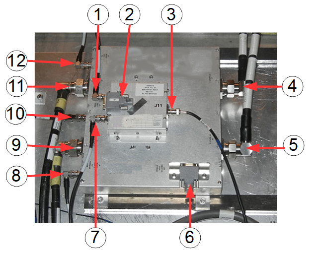
Item Description Item Description 1 J9 – Combiner LNA 1 input 7 J10 – Combiner LNA 2 input 2 J9 – HART ID for preamp/combiner 8 J6 – Body LNA 2 to preamp ASM 3 J11 – Combiner LNA output 9 J3 – Body coil 2 4 J1 – RF input 1 10 J7/J8 – BD bias 5 J2 – RF input 2 11 J2 – Body coil 1 6 J20 – HART ID for MR750 DTRSW 12 J5 – Body LNA 1 to preamp ASM -
- To replace a defective preamp combiner, remove the 4 screws
attaching it to the DTRSW.
Figure 2. Screws Attaching Preamp Combiner to MR750 DTRSW 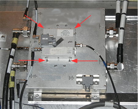
- If you are replacing the DTRSW, remove the preamp combiner first
as shown in Step 4. Remove the 4 screws holding the DTRSW to the outside of the magnet.
Figure 3. Screws Holding MR750 DTRSW 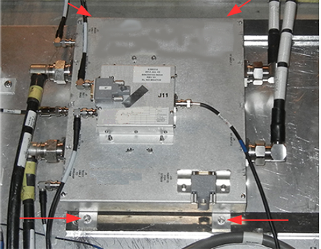
While carrying any module out of the magnet room, stay as far away from the magnet as possible.CAUTION 
Installing DTRSW or Preamp Combiner
Procedure
Secure the module, as follows:CAUTION -
For the DTRSW, secure the module to the magnet by tightening the four screws.
-
For the preamp combiner, secure the module to the DTRSW by tightening the four nuts.
-
Finalization
Procedure
- Replace the side covers.
- Remove LOTO from the PDM-RF power for the system. See MR Service Safety Manual, PN 5452735.
- Perform TR Dynamic Disable Calibration.
- If hardware was replaced, perform System gain calibration for body.
- Perform Dual Drive Quadrature Tool.
- Perform a body SNR test.
- Perform SaveInfo to save new calibration values.
- Complete a body and head test scan to make sure the system is functional.