• SIGNA MR355 / SIGNA MR360
  • Service Manual
  • 5856356-3EN Revision 5.0
  • Basic Service Documentation. Copyright General Electric Company.
  • Object ID: 00000018WIA30F98F20GYZ
  • Topic ID: id_13106280 Version: 4.0
  • Date: Feb 21, 2021 9:11:43 PM

Echo Planar Test (EPT)

Prerequisites

Table 1. Personnel requirements
Required personsPreliminary requirementsProcedureFinalization
1Not Applicable2 hoursNot Applicable
Table 2. Tools and test equipment
ItemQuantityEffectivityPart numberManufacturer
100-mm Sphere Phantom for 1.5T2-

46-317586G1

-
EPI Foam Positioner, Body1-

2170481

-
Grafidy Base Plate1-

46-271410G1

-
Head TLT Loader Positioner1-

5110241

-
Head Loader1-

46-287899G1

-
Table 3. Safety

Startup

About this task

EPT combines the functionality of the current B0 Dither Calibration, Group Delay Calibration and B0 Image Test into a single tool with a simple user interface. The output is suitable for remote support access, trending, and automatic checking of results against acceptance limits. In addition, EPT automatically updates the EPI calibration files when authorized by the user.

Procedure

  1. Click on New Pt, and enter the following:

    ID: geservice

  2. Place an EPI foam phantom holder and a 100-mm sphere phantom and phantom loader in the head coil, as shown in Figure 1Landmark on the center of the sphere, but do not advance to scan yet.
    Figure 1. EPI Phantom Positioning
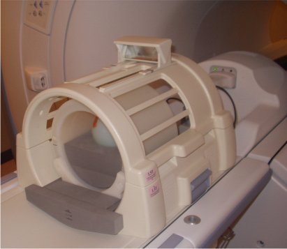
    Figure 2. Landmark Marker
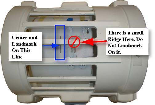
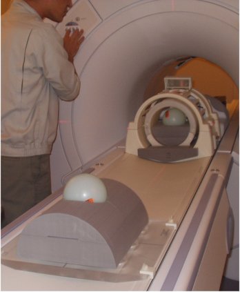
  3. Place an EPI foam phantom holder and a second 100-mm sphere on the Grafidy base plate, as shown in Figure 3. Move the table into the bore to 1100 mm from landmark. Slide the Grafidy base plate so the center of the 100-mm sphere is at the axial alignment light, and then press the MOVE TO SCAN button.
    Figure 3. Landmark 100–mm sphere phantom
    Note:
    When using the old head coil shown in Figure 1make sure phantom placement is correct prior to starting EPT by performing a 3-plane localizer scan. Before running the scan make sure that the offsets are set to zero, see Figure 4
    Figure 4. Scanning Range Offsets
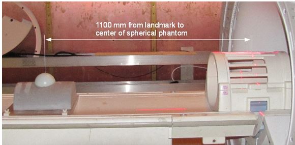
  4. Start the Echo Planar Test Calibration Tool.
    • Starting non-proprietary service tools:

      1. From the Common Service Desktop, select [Calibration] .

      2. Select [Echo Planner Test] from the calibration menu, and select [Click here to start this tool] to start the procedure.

      Figure 5. Starting EPT
  5. Click the Start button.
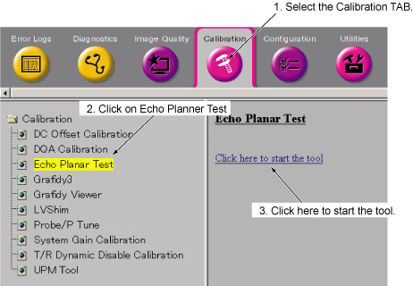
  6. The Echo Planar Test Window will appear, as shown inFigure 6 .
    Figure 6. Echo Planar Test Window
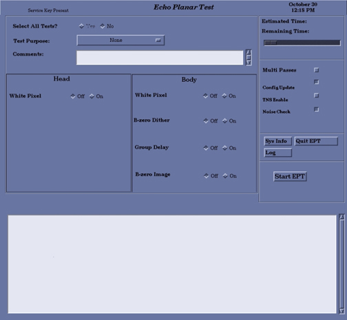
    Note:

    The “Select All Tests” default option is No.

  7. There are four option buttons on the screen that must be chosen before starting EPT:
    1. Selecting the Multi Passes button and entering an integer in the text box can perform more than one pass of the tests.
    2. One or more of the selected tests can automatically update the config files with new calibration data if the new data is within specs. Select Config Update before starting EPT.
  8. Select a Test Purpose from the pull-down menu.
  9. Two lines of comments can be entered, if desired. If no comments are entered, the text “NO COMMENT” will be entered into the results file.
  10. Select Start EPT. Running all the tests takes about one hour and will thoroughly test the EPI performance of your system. This is the recommended mode for baseline, PM, and initial problem-finding. The single test mode is meant to be used while troubleshooting. If possible, run the full set of tests at the end of your troubleshooting to verify system performance. While EPT is running, each test will be displayed in the message window indicating the amount of time the test requires to run.
    Note:

    Actual run time of the test may not coincide with the countdown clock displayed on the interface.

  11. EPT will create many images. If applicable, a window will pop up to inform you that there is not enough space available.
  12. When the tests are complete, one of four messages shown below will appear:
    1. Your tests completed successfully, or
    2. A minor system problem has been detected. This problem is NOT expected to affect image quality, or
    3. A serious system problem has been detected. This problem IS expected to impact image quality, or
    4. EPT was unable to determine PASS/FAIL status of the tests.
  13. If the tests completed successfully, proceed to Finalization below.
  14. If the tests fail, open the Report Manager to view the test results and identify the failing tests.
  15. Select Quit EPT and confirm

Image-based Short Cross Term Eddy Current Tool

About this task

If the B0 Image fails, check Shim and Grafidy, then quit EPT and run the Image-based Short Cross Term Eddy Current tool. This tool may reduce EPI ghosting and is designed specifically to work in conjunction with the EPT. If B0 Image passed, you may proceed to Test Termination Procedure. However, consider running the Short Cross Term Eddy Current Tool, because it may improve image quality.

Note: Consider running this test even if the B0 image passed. Based upon past experience, this may improve image quality.

Procedure

  1. To quit EPT, select Quit EPT.
  2. Open a C-shell and type /usr/g/bin/runsct.A message appears to verify EPT phantom setup. Click OK.The tool window appears.
  3. Click Apply and Scan.The tool first checks the eddy current compensation parameters. If the long cross-term compensation is not significant, the following message is displayed:The long xy alpha value (2 terms added) is: value. The correction would be too small to make improvement. Short cross term correction is not required. This tool does not need to be run.If this message appears, click Exit. The tool quits and the cross-term compensation is removed. Troubleshoot the system for other ghosting sources.
  4. If the system determines that correcting the short cross-term values may fix the ghosting problem, compensation is applied and the B0 Image scan starts with the new values. Data collection takes 10 to 15 minutes and the resulting ghosting level is measured and displayed.
    Note: To stop data acquisition and remove the short cross-term compensation values added by the tool, click Abort before test completion.
  5. If the B0 Image passes, the procedure is complete and the results are displayed. Click Exit and rerun the EPT tool. When running the tool, go to the Body section of the test options page and click Off next to B-zero Image (see Figure 6). This saves time by not rerunning this part of EPT.
  6. If the B0 Image results are not within specification, the cross-term compensation is removed. Click Exit and troubleshoot the system for other ghosting sources.
  7. After EPI ghosting problems have been brought into specification, rerun EPT and continue to Test Termination Procedure.

Test Termination Procedure

Procedure

  1. If Quit EPT is selected, a confirmation window appears.
  2. If the EPT process is not shut down in an orderly manner, the service protocol directions may need to be reset. This can be done by opening a C-shell and typing the following:

    cd /usr/g/service/cclass/ept Enter

    resetept Enter

Finalization

Procedure

  1. Reset the TPS to bring the system back into a known mode.
  2. Do a test scan to ensure the scanner is working properly before customer turn over.