
- SIGNA MR355 / SIGNA MR360
- Service Manual
- 5856356-3EN Revision 5.0
- Basic Service Documentation. Copyright General Electric Company.
- 00000018WIA301A4F20GYZ
- id_131058292.0
- Jul 19, 2019 11:00:21 AM
DTx Exciter
A minimum RF signal level from the DTx Exciter is required or else it will be impossible to meet the specified 10kW body and 2kW head RF power output levels. Use this section to verify that the DTx Exciter is outputting at least the minimum amount of power required to the CSA. See Table 1 for needed tools and test equipment.
| Item | Description | Part Number |
| 1. | RF Test Cable Kit | 46-255816G1 |
| 2. | Cannon to BNC-male Test Cable (included in item 4 below) | 46-301549P6 |
| 3. | SMB-female to BNC-male Test Cable (included in item 4 below) | 46-301549P5 |
| 5. | RF Power Measurement Kit (recommended) | 46-317724G1 or G2 |
| 6. | 100 MHz Scope (equivalent or greater) | 46-183029P61 |
| 7. | Excite 3 RF System Cabinet SV Cable Kit | 5117087 |
| 8. | Digital Volt Meter |
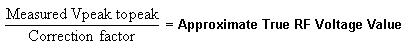
Please read the following if you do not have an RF Power Measurement Kit and you are going to attempt to measure the exciter output directly with a 100 MHz oscilloscope. Be aware that, due to oscilloscope bandwidth limitations, an exciter RF voltage reading taken directly from a 50 ohm terminated 100 MHz oscilloscope input channel can be as much as 16% less than the actual exciter RF output voltage level. This error is accounted for and is not a problem when using the oscilloscope in conjunction with the RF Power Measurement Kit. Reading reasonably accurate 63.86 MHz voltage levels directly from a 100 MHz oscilloscope without using the RF Power Measurement Kit requires that the correction factor of the scope channel being used is known. This is so that the approximate true RF voltage level can be calculated. The FE can request that the 63.86 MHz correction factor for each channel be determined and reported by the metrology lab the next time the oscilloscope is returned for calibration or, if the FE has access to the 4dBm (1 Vpp) oscilloscope calibrator tool used in the RF Power Measurement Kit, he can determine this correction factor himself. SeeScopes with Less Than 300 MHZ Bandwidth for more information concerning the derivation of the correction factor. Divide the Vpp value read from the oscilloscope by the correction factor to determine the approximate true RF voltage level value. The simple formula is as follows:
DTx Exciter RF Output Check Using The RF Power Measurement Kit
DTx Exciter RF Output Check
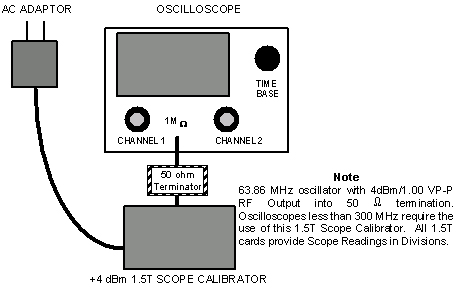
More accurate measurements are made by using the RF Power Measurement Kit and a 100 MHz oscilloscope. The kit will compensate for any amplitude error due to the bandwidth limitation associated with using a 100 MHz scope. The 1.5T Scope Calibrator provides a 63.86 MHz sine wave at 1.00 VPP (4dBm).
|
-
Verify that the Bandwidth Limit button is not selected on the oscilloscope.
-
Verify Channel 1 is set to 1 Mega ohm input termination.
Note:Use the 50 ohm terminator supplied with the RF Power Measurement Kit and set Channel 1 oscilloscope termination selection to 1Mega ohm.
-
Connect the 1.5T Scope Calibrator via the 50 ohm feed-through terminator to the oscilloscope input. See Figure 1 or the laminated card included in the RF Power Measurement Kit that is labeled, in the upper right-hand corner, CAL.
Figure 3. RF SIGNAL MEASUREMENTS USING A 300 MHZ OR CHARACTERIZED 100 MHZ SCOPE 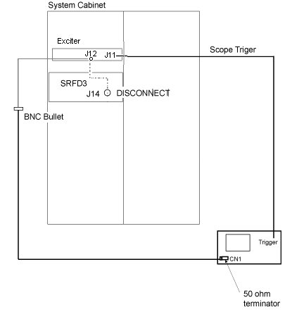
-
Adjust the channel 1 vertical Volts/div control until amplitude of the waveform is slightly greater than 8 divisions.
-
Adjust the channel 1 vertical Volts/div variable control to achieve exactly 8 divisions.
-
Remove 1.5T Scope Calibrator. Do not remove the 50 ohm feed-through terminator attached to the oscilloscope channel 1.
-
Disconnect the cable going to J14 of the CSA and connect it to the input of the 50 ohm terminator connected to channel 1 on the scope. A short ( less than 5 ft.) length of coax and a BNC bullet (female BNC/female BNC) adapter can be connected to the cable removed from J14 to route the signal to the scope.
-
Prepare the system to scan per Table 2.
-
Manual Prescan Scan TR. Increase TG to 200.
-
Confirm that the output from the J14 cable is > 31.77 minor divisions.
Note:Understand that each of the 8 divisions on the scope face is composed of 5 minor divisions. Since 8 X 5= 40 total minor divisions, count the number of individual minor divisions that the RF waveform spans. Since the input signal is small, minor divisions are used in place of divisions so that a more accurate scope measurement can be made.
-
Decrease TG to 0 (zero). Done.
-
Reconnect the cable removed from J14 of the CSA.
-
If the measured voltage meets the specification, then the Exciter is working properly. No need to continue this procedure. The functionality of CSA should be checked again.
If the measured voltage does not meet the specification, go to Cable Check between DTx Exciter (J12) and CSA (J14) to check the cable between DTx Exciter (J12) and CSA (J14).
Cable Check between DTx Exciter (J12) and CSA (J14)
This section will provide the instructions to check the RF coaxial cable between DTx Exciter (J12) and CSA (J14).
-
Prepare Digital Volt Meter (DVM)
-
Disconnect the RF coaxial cable from DTx Exciter J12 (MCX) and CSA J14 (BNC).
-
Connect 50 ohm terminator at the BNC connector of the cable.
-
At the MCX connector, measure the resistance between center pin and outer contact. The resistance is supposed to be 50 ohm.
If the resistance is 0 ohm or over 1 Mega Ohm, the cable is defective. Replace the cable.
-
Restore cable between DTx Exciter J12 (MCX) and CSA J14 (BNC).
-
If cable is ok, consider replacing the DTx Exciter.
DTx Exciter RF Output Measurement Using an Oscilloscope
DTx Exciter RF Output Measurement Using an Oscilloscope
-
Connect the oscilloscope to the system hardware as per Figure 3. Confirm that the oscilloscope is properly configured, that the channel 1 vertical Volts/div variable control is fully CCW, and that the bandwidth limit button on the oscilloscope is not selected.
-
Ensure that channel 1 is terminated with a 50 ohm feed-through terminator. Disconnect the cable going to J14 of the CSA module and connect it to the input of the 50 ohm terminator connected to channel 1 on the scope. A short ( less than 5 ft.) length of coax and a BNC bullet (female BNC/female BNC) adapter can be connected to the cable removed from J14 to route the signal to the scope.
-
Prepare the system to scan per Table 2.
-
Manual Prescan Scan TR. Increase TG to 200.
-
If using a scope with a bandwidth of 300 MHz or greater then read the peak to peak voltage from the scope face and confirm that it is > 0.796 Vpp (+2 dBm).
-
If using a < 300 MHz scope read the peak to peak voltage from the scope face and then, using the correction factor for the scope channel in use, calculate the approximate true RF voltage value by using the formula below. Confirm that the approximate true RF voltage value is > 0.796 Vpp (+2 dBm).

-
Decrease TG to 0 (zero). Done.
-
Reconnect the cable removed from J14 on the front of the CSA.
-
If the measured voltage meets the specification, then the Exciter is working properly. No need to continue this procedure. The functionality of CSA should be checked again.
If the measured voltage does not meet the specification, go to Cable Check between DTx Exciter (J12) and CSA (J14) to check the cable between DTx Exciter (J12) and CSA (J14).
Cable Check between DTx Exciter (J12) and CSA (J14)
This section will provide the instructions to check the RF coaxial cable between DTx Exciter (J12) and CSA (J14).
-
Prepare Digital Volt Meter (DVM)
-
Disconnect the RF coaxial cable from DTx Exciter J12 (MCX) and CSA J14 (BNC).
-
Connect 50 ohm terminator at the BNC connector of the cable.
-
At the MCX connector, measure the resistance between center pin and outer contact. The resistance is supposed to be 50 ohm.
If the resistance is 0 ohm or over 1 Mega Ohm, the cable is defective. Replace the cable.
-
Restore cable between DTx Exciter J12 (MCX) and CSA J14 (BNC).
-
If cable is ok, consider replacing the DTx Exciter.