
- SIGNA MR355 / SIGNA MR360
- Service Manual
- 5856356-3EN Revision 5.0
- Basic Service Documentation. Copyright General Electric Company.
- 00000018WIA30DD7F20GYZ
- id_131074402.0
- Jul 19, 2019 10:59:31 AM
Leveling Low Height Fixed Table and Top Height Adjustment
Prerequisites
| Required persons | Preliminary requirements | Procedure | Finalization |
|---|---|---|---|
| 1 | 0 minutes | 30 minutes | 0 minutes |
| Item | Quantity | Effectivity | Part number | Manufacturer |
|---|---|---|---|---|
| Standard Tool (Non Magnetic) | 1 | - | - | - |
| ||||
Leveling Low Height Fixed Table
Procedure
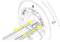
- Make sure that Inner (Lower) Scissors Cover is removed. If not,
remove it by referring to the illustration below.
Figure 1. Inner(Lower) Scissors Cover Removal 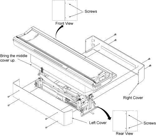
- Check Patient Table for levelness at four locations, both front-to-back
and left-to-right. This should be checked at the table top level,
not at the table base, since table top alignment is the critical factor.
Table height variation will be adjusted within 3mm.
Figure 2. Level at four locations 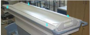
- Check the four Leveling Pads locations provided in the Base
weldments.
Figure 3. Four Leveling Pads 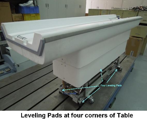
- Loosen four screws fixed table with dock frame.
Figure 4. Loosen four screws 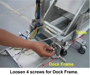
- Loosen the hand tightened Locknut of leveling pad.
Figure 5. Locknut 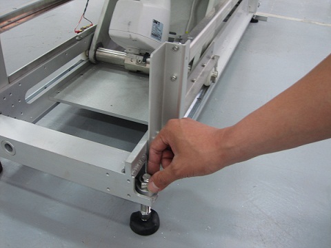
- Rotate the leveling pad stud by using 14mm spanner to adjust
the Table height valiance within 3mm at four locations shown in Figure 2.Note:
To raise the table height, turn the pad stud to anticlockwise direction. To reduce the Table Height, turn the pad stud to clockwise direction.
Figure 6. leveling pad stud 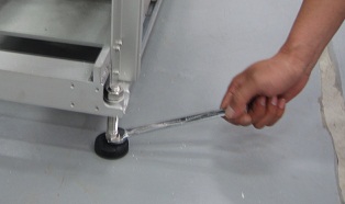
- The weldment height from the floor must be within 81+/-20 mm
for uniform Loading. Check it at all four locations
Figure 7. Weldment height 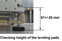
-
If the height is not within 81+/-20 mm, then adjust Leveling pads and level the Table height again by referring to Figure 6. (Turn leveling pads by same rotation numbers at four locations in this case.)
-
Top Height Adjustment
Procedure
- Measure the height difference between the Guide ridge (cradle
rolling area) of Tabletop and guide ridge (cradle rolling area) of
the bridge.
- Rotate the leveling pad stud by same rotation number at four
location using 14mm spanner by checking the height difference between
the Guide ridge (cradle rolling area) of Tabletop and guide ridge
(cradle rolling area) of the bridge.Note:
To raise the table height, turn the pad stud to anticlockwise direction. To reduce the Table Height, turn the pad stud to clockwise direction.
Figure 8. leveling pad stud - Confirm that table height variation is with 3mm at four location.
Figure 9. Level at four locations - Confirm that the weldment height from the floor is within 81+/-20
mm at four locations.Note:
The weldment height from the floor must be within 81+/-20 mm for uniform Loading.
Figure 10. Weldment height - Once the Table Height Variation is adjusted within 3mm, and
the table top is aligned against the bridge, then lock the Leveling
Pad Lock nut by hand.
Figure 11. Lock the Leveling Pad Lock Nut
Finalization
No finalization steps.