- id_12374061
- Version: 1.33
- Date: Jan 27, 2020 12:16:26 PM
XRMw Gradient Coil Replacement
Prerequisites
| Required persons | Preliminary requirements | Procedure | Finalization |
|---|---|---|---|
| 3 | Not Applicable | 8 hours | Not Applicable |
| Item | Quantity | Effectivity | Part number | Manufacturer |
|---|---|---|---|---|
| Extension Cord | 1 | - | - | - |
| Non-Absorbent Protective Clothing (long sleeve shirt and pants, one per person) | 1 | - | - | - |
| PPE: Non-Magnetic Safety Shoes, Safety Glasses and Gloves | 1 | - | - | - |
| Non-Magnetic Field Mapping Fixture Kit | 1 | - |
5266042-4 |
- |
| Coolant Removal Pump Kit | 1 | - |
5269683 |
- |
| B0 Power Supply | 1 | - |
2141701 |
- |
| Non-Magnetic Tool Kit | 1 | - |
5112581 |
- |
| Non-Magnetic Torque Wrench | 1 | - |
5534134 or 5537507 |
- |
| 5 gallon Bucket | 1 | - |
2239133 |
- |
| Nitrile Gloves | 1 | - |
46-194427P400 |
- |
| Floor Sign, Warning: Authorized Personnel Only (included with Safety Signage Kit 46-258770G4) | 1 | - |
2289812 |
- |
| Long Room Gray Coil Cart with Cradle (2,444 mm) | 1 of either cart | - | 2144093 | - |
| Short Room Blue Coil Cart with Cradle (2,416 mm) | - | 2144093-2 | - |
| Item | Quantity | Effectivity | Part number | Manufacturer |
|---|---|---|---|---|
| Isopropyl Alcohol, 70%, USFS-200 | 1 | - | - | - |
| Scotch Brite Pad | As needed | - | - | - |
| Cable Ties | 100 | - |
46-252283P68 |
- |
| Red Loctite 271 (Check expiration date.) | 1 | - | - | - |
| Never Seize | AR | - |
46294151P8 |
- |
| Blue Loctite 243 (Check expiration date.) | AR | - |
5415261-2 |
- |
| Clean Lint-Free Towels (Kimwipes) | AR | - | - | - |
| XRMB Coolant Fluid (approximately 15 gallons of coolant required for each XRMB installation) | 4 cartons of four, one gallon containers | - |
5174313-4 |
- |
|
| Condition | Reference | Effectivity |
|---|---|---|
|
Before beginning this procedure, at least one person must complete the training course, GEHC-TECH-AMOL-CT530-01_CURR. |
- | - |
Overview
Preliminary Tasks
Procedure
- Order the nonmagnetic torque wrench before starting this procedure.
- Refer to the MR Service Safety Manual, Direction 5452735, and perform LOTO on:
-
PGR PDU/Gradient Subsystem
-
Heat Exchanger Cabinet (HEC)
-
- notice
- If the magnet is ramped, remove all passive shim trays from the XRMw Gradient Coil before the installation and store them in a safe place. (Procedure for replacing shim trays can be found in the Magnet and Cryogen Manual for Passively Shimmed Magnets, Direction 5495018.)
 |
Coolant Removal
Procedure
 caution
- LOTO should already be applied to the HEC. (Refer to the MR Service Safety Manual, Direction 5452735.)
- note:Turn off PVC valves in coolant supply and return lines at the service end of the Gradient Coil.
Wear nitrile gloves and safety glasses when removing coolant.
- Place an empty five gallon bucket close to the service end for discharged coolant.
- caution
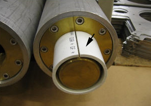
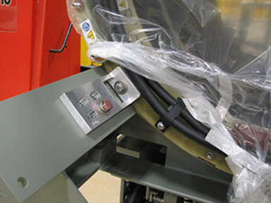
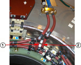
- The connection between hose and fitting is pressure only. To properly remove a hose from the fitting, carefully cut a slit (1) on the manifold hose (avoid damaging the water fitting), and slide it off the barb to disconnect the supply manifold from the fitting.
- Repeat for the return line.
- Retain the fittings at the site.
Figure 1. Barb Fitting and Valve
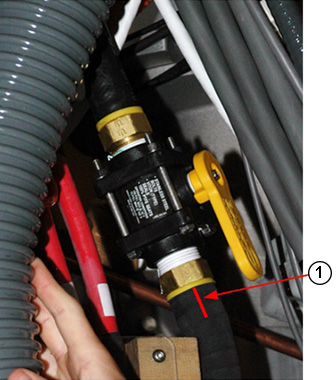
- note:To remove the Gradient Coil manifold hoses from the PVC valves, use wrenches to unthread the barb fitting from each PVC valve.
Do not cut the barb fittings out of the hoses unless the Gradient Coil needs to be drained and returned. This process ensures there will be enough hose length to reconnect the fitting to the valve.
- Detach the copper block from the magnet.
- notice
- Slowly disconnect the supply, then the return manifold from the valve, and drain the fluid into the bucket.
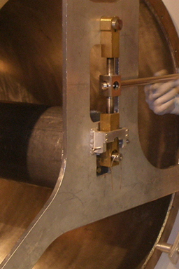
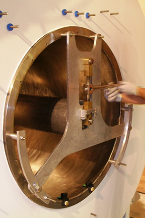
Figure 2. Draining Manifold Coolant

- Disconnect the coolant inlet and outlet lines from the Gradient Coil, and connect the air hose from the manual pump to the water supply line on the coil.
- Operate the air pump while observing the coolant draining from the Gradient Coil; continue draining the coolant until there is no significant flow at the outlet draining into the container. (Should take about five minutes.)
- Follow local regulations and the customer’s procedure for proper disposal of the coolant.
- Join the supply and return manifold together using a cable tie and kink if necessary. (This forms a closed loop so coolant does not spill out during Gradient Coil removal.)
 |
|
|
Cable Removal and Bus Bar Cable Disconnection
Procedure
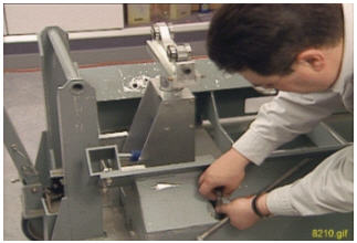
- Remove and discard the six flanged M10 nuts and Nord-Lock washers securing the bus bar lugs to the Gradient Coil, and slide the bus bar terminal lugs off the coil studs.
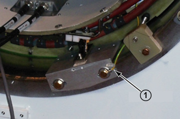
Figure 3. Y and XZ Bus Bar Cable Connections
- Remove the following cables from the Gradient Coil:
-
Temperature sensor cable at the rear of the magnet
-
Ground wire (1)
-
Preparation for XRMw Coil Removal
Procedure
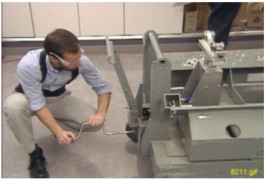
- Attach three Adapter Plates (5338222) to the patient end of the Gradient Coil at 3, 9, and 12 o'clock positions with M10 x 20 mm bolts and M10 nuts.
Figure 4. Bolt with Nut
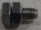
- Attach two Adapter Plates (5338223) to the service end of the Gradient Coil at the 3 and 9 o'clock positions with M10 x 20 mm bolts and M10 nuts.
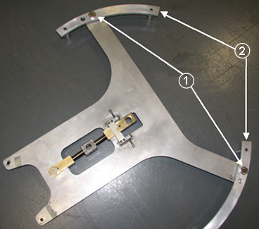
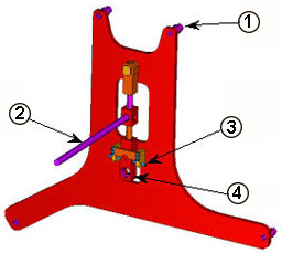
- Retrieve the Mounting Plates, 5161985 (1) and 5161983 (2) and the two Tube Guide Roller Assemblies, 5308402 (3) from the Gradient Coil Insertion and Lift Kit shipping crate, and securely attach the roller assemblies to the mounting plates.
Figure 5. Roller Assemblies and Mounting Plates
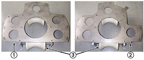
Item Description 1 Mounting Plate, Patient End 2 Mounting Plate, Service End 3 Roller Assemblies - Attach the Adapter Plate (5338224) to the service end of the Gradient Coil at the 12 o'clock position with M10 x 20 mm bolts and M10 nuts.note:
Different adapter plates are used for the front and rear of the Gradient Coil.
- notice
- Align the mounting holes on the patient end of the Mounting Plate (5161985) with those in the Adapter Plate (5338222), includes the guide roller assemblies already attached to the Gradient Coil, and secure them using the M10 x 20 mm bolts and M10 nuts.
Figure 6. Mounting Plate with Roller Assemblies (Patient End)
- Align the mounting holes on the service end Mounting Plate (5161983) with those in each Adapter Plate (5338223 and 5338224), already attached to the Gradient Coil, and secure them using M10 x 20 mm bolts and M10 nuts.
Figure 7. Mounting Plate with Roller Assemblies (Service End)
- Retrieve the Tube Support Plate Assembly (2284928-2) from the Gradient Coil Insertion and Lift Kit shipping crate, and remove the two lower standoffs (1) from the tube support plate.
- Attach the Wing Adapters, 5339882 (2) to the tube support plate with stainless steel 0.75 in. 16 x 1.25 in. long bolts.
Figure 8. Support Plate with Wing Adapters
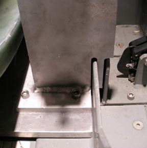
- Attach the tube support plate (1) to the magnet service end by inserting the 100 mm M10 x 25 stainless steel studs (5303994) 3/8 inch (13 mm) into the magnet, and secure them with the stainless steel washers and M10 nuts from the Gradient Coil Insertion and Lift Kit.note:
Make sure the six extension spacers face toward the magnet interface ring and the nuts are securely tightened.
Figure 9. Support Plate Attached on Interface Ring
|
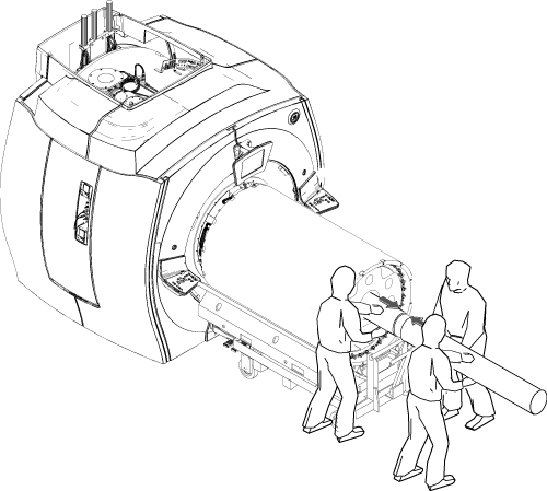
XRMw Coil Removal with Cart
Procedure
- warning
- notice
- Place the Tube Jacking Assembly (5191132) in the cart, making sure the back of the jack assembly fits properly into the cart.
Figure 10. Jack Assembly Placement
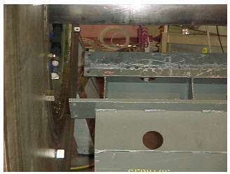
- Maneuver the cart to the patient end of the magnet, and position it in front of the magnet with at least a 2 in. (50.8 mm) gap between the cart and the magnet interface ring (required for lower wedge removal.)
Figure 11. Gap Between Magnet and Cart
- Center the cart left-to-right with respect to the magnet bore, and adjust the height of the cart to match the magnet opening.
- Release the hand lever on the cart handle to set the brakes, which keeps the cart from moving after the cart is aligned with the bore.
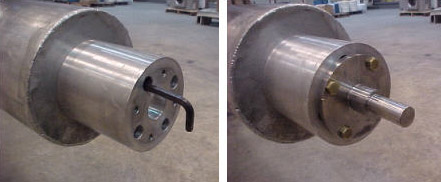
- Retrieve the male Insertion Tube (2284929) and tube Standoff (5191626).
- Attach the tube standoff to the male insertion tube using the 4 inch, 0.375–16 UNC hex socket screw (5303993) included in the Gradient Coil Insertion and Lift Kit.
- After the standoff is secured to the tube, attach the tube pilot shaft to the standoff.
Figure 12. Attaching Standoff to Insertion Tube
- Remove the PVC shield from the brass thread of the male insertion tube.
Figure 13. PVC Shield for Brass Thread
- Slide the male insertion tube through the tube guide roller assemblies at both sides of the Gradient Coil, push the pilot shaft through the support plate mounting bearing, and insert a nonmagnetic safety pin through the hole in the pilot shaft.
Figure 14. Tube Pilot Shaft and Support Plate
- notice
- With one person holding the male insertion tube to keep it from rolling, two people should obtain the female insertion tube from the shipping crate and thread the two tubes together.note:
Each of the two pieces of the gradient insertion tool weighs less than 35 lb. (15.9 kg).
Figure 15. Setting Up Insertion Tube Assembly
- notice
- Recheck the centering of the cart left-to-right with respect to the magnet bore, and adjust the longitudinal alignment of the cart if required.
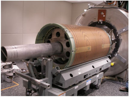
- Simultaneously raise the tube jack and the support plate mounting bearing to lift the Gradient Coil.
Figure 16. Raising XRMw Gradient Coil
- While keeping the coil as close to level with the magnet bore, lift the coil high enough to remove the gradient mounting pads, and remove them from each end of the magnet.
- Lower the Gradient Coil and adjust it left-to-right, as necessary, to keep it centered within the magnet bore.
- Slowly push the Gradient Coil out of the magnet bore while watching the clearances to the left, right, top, and bottom; adjust the tube jack and support plate mounting bearing as required to keep the coil from touching the magnet bore surface.
- Rotate the Gradient Coil until the return coolant line at the service end is oriented downward.
- Gradually lower the tube jack and the support plate mounting bearing until the weight of the Gradient Coil settles on the cart.
- caution
- Properly secure the Gradient Coil to the coil cart with Bracket (5357473).
- caution
- Remove the insertion tool from the Gradient Coil.
- With three people, move the Gradient Coil and cart out of the Magnet Room.
|
|
|
|
|
Preparation Before XRMw Installation
Procedure
- While wearing nitrile gloves, wipe the magnet bore using a clean towel and isopropyl alcohol.
- Examine the electrical connection terminals at the Gradient Coil service end.
- Inspect the copper terminal surface and the stud thread of the gradient terminals for gauges, surface damage, and any epoxy or threadlocker contamination.
- If necessary, clean with an abrasive pad and wipe with alcohol wipes.
- Remove the shipping brackets securing the Gradient Coil to the cart.
Figure 17. XRMw Shipping Bracket(s)
- Remove the Gradient Coil cradle fasteners (two per side) from the cradle.
Figure 18. Removing Cradle Fasteners
- Use a vacuum cleaner to remove any possible metal dust/shavings from inside and outside of the Gradient Coil.
- Retrieve the Mounting Plates, 5161985 (1) and 5161983 (2) and the two Tube Guide Roller Assemblies, 5308402 (3) from the Gradient Coil Insertion and Lift Kit shipping crate, and securely attach the roller assemblies to the mounting plates. (See Figure 5.)
- notice
- Align the mounting holes on the patient end of the Mounting Plate (5161985) with those in the Adapter Plate (5338222), includes the guide roller assemblies already attached to the Gradient Coil, and secure them using the M10 x 20 mm bolts and M10 nuts.
Figure 19. Mounting Plate with Roller Assemblies (Patient End)
- Align the mounting holes on the service end of the Mounting Plate (5161983) with those in each Adapter Plate (5338223 and 5338224), already attached to the Gradient Coil, and secure them using M10 x 20 mm bolts and M10 nuts.
Figure 20. Mounting Plate with Roller Assemblies (Service End)
- Retrieve the male Insertion Tube (2284929) and tube Standoff (5191626) shown in Figure 12 and proceed.
- Attach the tube standoff to the male insertion tube using the 4 inch, 0.375–16 UNC hex socket screw (5303993) included in the gradient coil insertion and lift kit.
- After the standoff is secured to the tube, attach the tube pilot shaft to the standoff.
- Remove the PVC shield (shown in Figure 13) from the brass thread of the male insertion tube.
|
XRMw Gradient Coil Installation
Procedure
- Retrieve the tube Support Plate Assembly (2284928-2) from the Gradient Coil Insertion and Lift Kit shipping crate, and make sure the Y Gradient Cables are removed from the magnet.
- Make sure the two Wing Adapters (5339882) are attached with 0.75 inch, 16 x 1.25 in. long stainless steel bolts (1).
- Secure the tube support plate assembly and wing adapters to the magnet flange at the service end with M10 studs, spacers, and M10 nuts (2).
Figure 21. Attaching Tube Support Plate
- Adjust the horizontal adjustment screws (3) on the tube support plate assembly until the tube support bearing (4) is centered left-to-right.
Figure 22. Adjusting Support Plate
Item Description 1 Spacer 2 Vertical Adjustment Lever 3 Horizontal Adjustment Screws 4 Support Bearing - warning
- Place Tube Jacking Assembly (5191132) in the cart, making sure the back of the jack assembly fits properly into the cart. (See Figure 10.)
- Maneuver the cart and Gradient Coil to the patient end of the magnet, and position it in front of the magnet with at least a 2 in. (50.8 mm) gap between the cart and the magnet interface ring (required for lower wedge removal) shown in Figure 11.
- Center the cart left-to-right with respect to the magnet bore.
- Release the hand lever on the cart handle to set the brakes, which keeps the cart from moving after the cart is aligned with the bore.
- Raise or lower the cradle of the cart as required to vertically align the tube support plate at the magnet and the gradient mounting plates at the Gradient Coil.
Figure 23. Adjusting Cart Height
- Slide the male insertion tube through the tube guide roller assemblies at both sides of the Gradient Coil, making sure the end with the standoff and pilot shaft faces toward the magnet.
- notice
- With one person holding the male insertion tube to keep it from rolling, two people should obtain the female insertion tube from the shipping crate and thread the two tubes together.
Figure 24. Setting Up Insertion Tube Assembly
- notice
- Push the complete insertion tube assembly into the magnet bore so the tube pilot shaft is close, but not touching, the tube support plate.
Figure 25. Complete Insertion Tube Assembly
- Align the support plate mounting bearing with the tube pilot shaft by adjusting the vertical height of the support plate bearing using the stainless steel lever, and/or raising or lowering the cart.
- Recheck the centering of the cart left-to-right with respect to the magnet bore, and adjust the cart longitudinal alignment if required.
- Push the pilot shaft through the support plate mounting bearing, and insert a nonmagnetic safety pin through the hole in the pilot shaft. (See Figure 14.)
- Raise the tube jack and support plate mounting bearing to lift the Gradient Coil up, while keeping the coil level with the magnet bore as shown in Figure 16. (Coil should be able to rotate freely when completely lifted off the cart.)
- Rotate the Gradient Coil, if necessary, until the electrical connection terminals at the XRMw service end are oriented upward.
- Slowly push the Gradient Coil into the magnet bore while watching the clearances to the left, right, top and bottom; adjust the tube jack and support plate mounting bearing as required to keep the coil from touching the magnet bore surface.note:
Keep hands and loose clothing away from the bore as the coil is being moved into the magnet bore.
- After the wedge is fitted firmly into the slot, secure it to the Gradient Coil flange using one G10 washer (5146169) and one brass hex-head M10 x 35 screw (5110638-65).
- Shake the bottle, then apply Loctite 271 to the engagement portion of the brass bolt.
- Securely tighten the brass bolt to each wedge to a torque of 13 N m to 16 N m (10 ft lb to 12 ft lb), in the order installed, and onto the axial stops.
- If a bolt appears to be bottomed out, use a second G10 washer. Do not use more than two washers on any location.
- Ensure there is a gap between the wedges and the Gradient Coil flange after tightening the bolts.
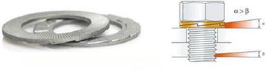
- note:Reinstall the bus bar cables to the new Gradient Coil, placing a new Nord-Lock washer over each stud.
Observe the following:
-
Always use the new Nord-Lock washers that come with the FRU package. Do not reuse the old Nord-Lock washers and stainless steel flanged nuts.
-
Nord-Lock washers consist of two pieces, which are generally glued together. Always use a complete set with two pieces joined together in correct orientation. Do not use a separated single piece.
Figure 26. Nord-Lock Washer Configuration
-
Inspect the Gradient Coil terminal surface for contaminants or gouges, and clean the surface before installing the bus bar terminal.
-
- notice
- After positioning the cable connection on the stud, place a new Nord-Lock washer over each stud.
- Shake the bottle, place two drops of Loctite 243 on the exposed thread, but avoid getting Loctite on the Nord-Lock washer.
Figure 27. Loctite on Stud
- Hand tighten the nut.
- Discard the old washers.
- Shake the bottle, place two drops of Loctite 243 on the exposed thread, but avoid getting Loctite on the Nord-Lock washer.
- danger
- notice
- Set the torque wrench to 25 ft-lb. (33.9 Nm), and install the 15 mm socket onto the extension.note:
Make sure that the arrow on the torque wrench is visible. If the arrow is not visible, the torque wrench will not click when the proper torque is reached.
Figure 28. Arrow on Non-magnetic Torque Wrench
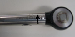
- Torque the nut in the direction of the arrow until the torque wrench reaches the break point.
- To designate the torque position, use a marker to make a line from the base of the stud to the nut (1).
Figure 29. Torque Marking on Stud and Nut
- Repeat this process for all stainless steel flanged nuts.
- Torque each nut a second time to confirm proper torquing. If the nut moved more than one flat from the original position, retorque the nut a third time.note:
If retorquing is required, mark a new line on the nut and stud.
- To connect the XRMw Coil manifold:
- Remove the copper block and hose assembly from the removed Gradient Coil, and replace the 165 mm (1) and 150 mm (2) hoses with pieces cut from the hose material provided in the replacement gradient kit.
Figure 30. Return Outlet and Supply Inlet Hoses
- Secure the hose pieces at the nylon elbows with Hose Clamps (46-252065P155), then fully cover the hose clamps with a few wraps of the linerless rubber Splicing Tape (46-294167P91) or electrical tape.
- Reinstall the copper block on the magnet, and connect the large diameter hoses to the PVC valves.
- Before pushing the 165 mm hose onto the hose barb elbow, slide a Hose Clamp (46-252065P155) over the end of the hose.
- Push the 165 mm hose onto the nylon hose barb elbow for the Gradient Return Outlet, and secure the hose in place with the hose clamp.
- Fully cover the metal hose clamp using a few wraps of the splicing or electrical tape.
- Repeat the above steps to connect the 150 mm hose to the Gradient Supply Inlet.
- Recharge the system with coolant and check for leaks. (Refer to XRMw Manifold Replacement.)
- Remove the copper block and hose assembly from the removed Gradient Coil, and replace the 165 mm (1) and 150 mm (2) hoses with pieces cut from the hose material provided in the replacement gradient kit.
|
|
|
|
|
Finalization
Procedure
- Remove all parts of the gradient Insertion Tool from the XRMw Gradient Coil and return them to the crate; properly store all components.
- warning
- Reinstall all passive shim trays into their proper slots. (Procedure for replacing shim trays can be found in Magnet and Cryogen Manual for Passively Shimmed Magnets, Direction 5495018.)
- Connect the B0 power supply to connection P304-1 on the magnet, plug the B0 tester into AC power, and quench the B0 coil in the magnet by depressing and holding the white button for at least one minute.
- Perform passive shimming, referring to Magnet and Cryogen Manual for Passively Shimmed Magnets, Direction 5495018.
- Remove LOTO from the PGR PDU/Gradient subsystem and the HEC, referring to the MR Service Safety Manual, Direction 5452735.
- Reconnect the manifold of the Gradient Coil to the supply and return lines.
- Refer to HEC Coolant Fill and Coolant Leak Check to add coolant to the Heat Exchanger (HE) reservoir, turn on the HE pumps, and check the coolant system for leaks. (The volume added should be close to that of the drained coolant.)
- Perform the following calibrations:
- Perform a SaveInfo, using the Save and Restore Tool, to capture new calibration values.