- id_12374900
- Version: 1.4
- Date: Jul 5, 2019 10:03:32 PM
XRMw Manifold Replacement
Prerequisites
| Required persons | Preliminary requirements | Procedure | Finalization |
|---|---|---|---|
| 1 | Not Applicable | 8 hours | Not Applicable |
| Item | Quantity | Effectivity | Part number | Manufacturer |
|---|---|---|---|---|
| Safety Glasses (one pair per person) | 1 | - | - | - |
| Floor Sign, Warning: Authorized Personnel Only | 1 | - |
Included in Safety Sign Kit 46-258770G4 |
- |
| Coolant Removal Kit (part of HEC) | 1 | - |
5269683 |
- |
| Non-Magnetic Tools Kit | 1 | - |
5112581 |
- |
| 5 Gallon Pail | 1 | - |
2239133 |
- |
| Nitrile Gloves | 1 | - |
46-194427P400 |
- |
| Item | Quantity | Effectivity | Part number | Manufacturer |
|---|---|---|---|---|
| Coolant Fluid (1 Gallon Container) (see Required Conditions) | 15 | - |
5174313 |
- |
| Coolant Fluid (5 Gallon Container) (see Required Conditions) | 3 | - |
5174313-2 |
- |
| Coolant Manifold Replacement Kit | 1 | - |
See FRU Manual |
- |
| Item | Quantity | Effectivity | Part number | Manufacturer |
|---|---|---|---|---|
| XRMw Manifold | 1 | - | - | - |
|


| Condition | Reference | Effectivity |
|---|---|---|
|
Approximately 4 gallons of coolant fluid is needed for each manifold replacement. FEs must decide which type of container to order. |
- | - |
|
Power to the PGR cabinet must be turned off and LOTO procedures must be implemented. See the MR Service Safety Manual, PN 5452735. |
- | - |
|
Coolant circulation pump must be turned off and LOTO procedures must be implemented. See the MR Service Safety Manual, PN 5452735. |
- | - |
Overview
This procedure requires disposal of coolant. Inform the customer that coolant disposal is needed and then follow the proper customer coolant disposal procedure.
XRMw Coil Water Removal
Procedure
- note:Remove the patient bridge. See Bridge and Longitudinal Drive Belt Replacement.
Wear nitrile gloves when performing coolant removal.
- Remove the magnet rear end bell. See Rear End Bell Removal and Install.
- Turn off the pumps at the Heat Exchange Cabinet (HEC) by pressing the appropriate key sequence
for the blowers, gradient coil, and power electronics drives. See Table 7.note:
Do not remove power from the VFDs (Variable Frequency Drive) without first powering down using the key sequences shown in Table 7. Failure to follow this power-down process may result in premature VFD failure.
Table 7 HEC Control Panel Key Sequence Part Key Sequence Blowers ▲ F1 Gradient Coil (GC) ▲ F2 Power Electronics (PE) ▲ F3 Press and hold ▲ while selecting the F-number key.
- Perform LOTO on the HEC. See the MR Service Safety Manual, PN 5452735.
- Perform LOTO on the PGR PDU/gradient subsystem. See the MR Service Safety Manual, PN 5452735.
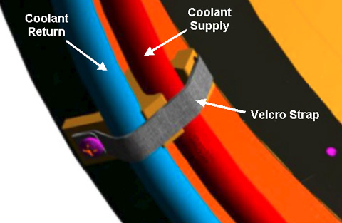
- Turn off both PVC valves in the coolant supply and return lines at the service end of the XRMw coil.
- Place an empty five gallon bucket close to the magnet service
end to hold discharge coolant.
Figure 1. Draining Manifold Supply

- Carefully disconnect the manifold supply and return lines (one at a time) from the barbed connections below the closed valves. Direct one line (either the supply or return line) toward the bucket and empty as much coolant as possible into the bucket.
- Obtain a one inch barbed fitting from the Coolant Removal Kit and attach it to the other line. Connect the pump-to-manifold adapter to the other line through the barbed fitting.
- Attach the manual pump from the Coolant Removal Kit to the other end of the adapter (if not attached already).
- Start pumping air while watching the coolant discharge.
- Continue pumping until no more coolant comes out. This takes about 10 to 15 minutes.
Old Manifold Removal
Procedure
- With the magnet rear end bell and the rear pedestal removed, the XRMw manifolds are accessible.
- Ensure that both PVC valves in the coolant supply and return lines at the XRMw service end are turned off, and coolant has been purged from the XRMw coil.
- Remove the eight black anchor Velcro straps securing the manifolds
to the XRMw coil.
Figure 2. Velcro Strap
- notice
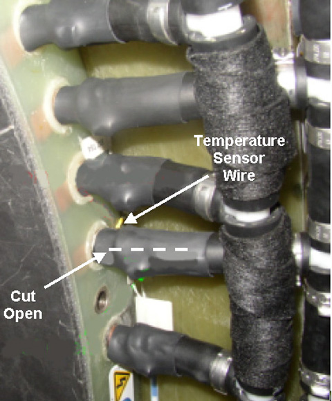
- Using a non-magnetic side cutter, carefully cut open the heat
shrinks at the manifold-to-inner coil connections, making sure not
to cut the temperature sensor and wire when removing the heat shrink.
Figure 3. Removing Heat Shrink
- After the heat shrink is removed, the stainless steel hose clamp is exposed. If it is a crimped clamp, it cannot be opened with a screwdriver. Use a combination of non-magnetic screwdriver and needle-nose pliers to push the clamp away from the coil and slide it towards the flexible hose
- notice
- After the hose clamp is open or pushed off the copper tube terminal, disconnect the manifold hose from the tube terminal.
- Repeat Step 4 through Step 6 to disconnect all manifold hoses from XRMw inner coil.
- Disconnect the manifold tubes from the copper fittings.
 |
|
New Manifold Installation
Procedure
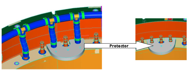
- Use the Temperature Sensor Protector (5352243, included in FRU
kit) to ensure the manifold will not damage the external temperature
sensors when pushing the manifold extension hoses onto the copper
terminals.
Figure 4. Temperature Sensor Protector
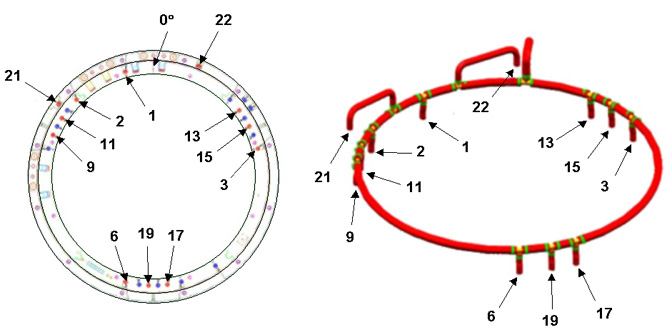
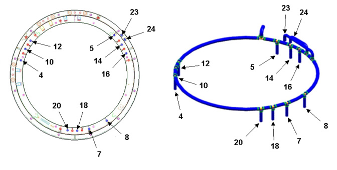
- Assemble the XRMw Manifold Coolant Return (5339472) on the coil.
Corresponding hoses and coil locations are shown below.
Insert a stainless steel hose clamp (46-252065P155) on each manifold leg before pushing the hoses into position, and make sure that all hose clamps are in a similar orientation.
Figure 5. XRMw Manifold Coolant Return
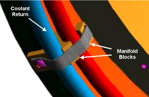
- Make sure the manifold return assembly is in the correct position
and sitting on the lower position of the manifold blocks.
Figure 6. Manifold Coolant Return and Manifold Blocks
- Assemble the XRMw Manifold Coolant Supply (5339471) on the coil.
Corresponding hoses and coil locations are shown below.
Figure 7. XRMw Manifold Coolant Supply
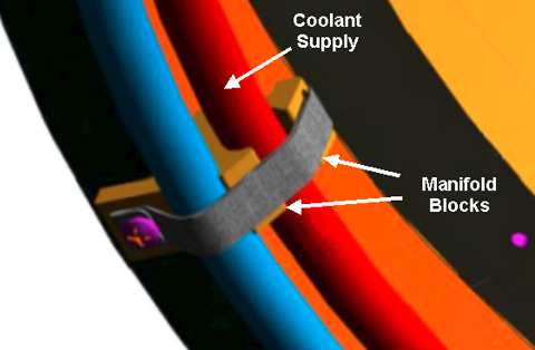
- Make sure the XRMw manifold coolant supply is in the correct
position and sitting on the upper position of the manifold blocks.
Figure 8. Manifold Coolant Supply and Manifold Blocks
- Tighten all hose clamps. Use a wrench (not a screwdriver) to make sure all connections are tight.
- Tighten the Velcro straps.
- Apply rubber splicing tape (46-294167P91, provided with the manifold replacement kit) to the clamps and any exposed copper tube terminals.
- Connect the supply and return manifold to the barbed fitting of the main coolant lines on the magnet.
- Secure the connection with stainless steel hose clamps.
- Open the main coolant valve.
Finalization
Procedure
- Remove LOTO from the PGR PDU/gradient subsystem. See the MR Service Safety Manual, PN 5452735.
- Refer to HEC Coolant Fill and Coolant Leak Check to add coolant to the heat exchanger reservoir, turn on the heat exchanger pumps, and check the coolant system for leaks. The volume added should be close to that of the discharged coolant.
- Restore the magnet rear end bell. See Rear End Bell Removal and Install.
- Refer to Bridge and Longitudinal Drive Belt Replacement to restore the rear pedestal by attaching the rear pedestal to the magnet with the two bolts.
- Perform a check scan to ensure the system is functioning correctly.