Removing the Integrated Control Engine (ICE) from the System Cabinet.
Prerequisites
Personnel requirements
Required persons
Preliminary requirements
Procedure
Finalization
1
-
30 minutes
-
Tools and test equipment
Item
Quantity
Part number
Manufacturer
Nonmagnetic Titanium Service Tool Kit, Small Set
1 Kit
5113258
-
Nonmagnetic Titanium Service Tool Kit, Large Set
5112581
-
Procedure
Notice
Risk of ICN damage
The ICNs have software running on disk drives that can be corrupted if not shut down properly. Failure to properly power down an ICN can also result in premature ICN failure.
NEVER use the power button on the front to turn an ICN ON/OFF. Follow the procedure referenced below for removing power to the ICN chassis.
From the Common Service Desktop, turn off the ICN(s) (see ICN On/Off Procedure).
Do LOTO for reconstruction equipment. See the latest revision of the MR Service Safety Manual (5452735), available from the online documentation library.
Open the PGR door.
Connect the ESD strap to the side bracket.
Remove the ICE as follows:
Disconnect all connectors from the front panel.
Remove the screws securing the ICE module in place.
Carefully move the cables out of the way, and slide the ICE out.
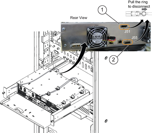
Disconnect the PCIe cable (J55) from the ICE rear panel.
Note: The PCIe cable is connected to J51 on systems with ICE for Digitized Per Pin (DPP).
Note: Disconnect the PCIe cable as the ICE is sliding out.
Figure 1. Disconnecting the PCIe cable
1
ICN PCIe connection for DPP
2
ICN PCIe connection for Remote Receiver (RRx)
Press the release tabs in on each side and pull the ICE forward.
Note: Hold the ICE carefully when you remove it so that it does not fall.
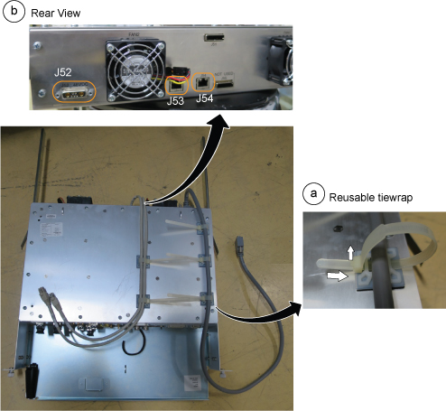
Remove the cables from the rear panel as follows:
Release all reusable tie wraps, and remove cables. (Lift up the latch and push the tie wrap to release it.)
Disconnect two Ethernet cables (J53, J54) and the power cable (J52) from the ICE rear panel.
Figure 2. Ethernet cables (J53, J54) and power cable (J52)
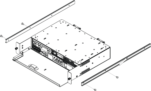
Detach the slide rails from the ICE High Level Assembly (HLA) and install them to the new FRU.
Figure 3. Slide rails
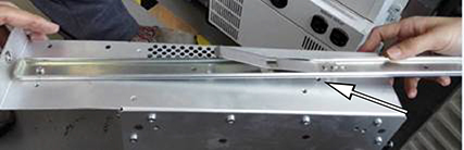
Note: When you install the slide rail on the side of the ICE, install the screw near the rear of the ICE in the hole shown below. This keeps the rail straight.Figure 4. Screw installed through slide rail

 Note: When you install the slide rail on the side of the ICE, install the screw near the rear of the ICE in the hole shown below. This keeps the rail straight.