
- 00000018WIA3020D030GYZ
- id_123749241.4
- May 22, 2020 3:59:06 PM
CFB Replacement
Prerequisites
| Required persons | Preliminary requirements | Procedure | Finalization |
|---|---|---|---|
| 1 | Not Applicable | 30 minutes | 30 minutes |
| Item | Quantity | Effectivity | Part number | Manufacturer |
|---|---|---|---|---|
| Standard Tool Kit | 1 | - | - | - |
| Item | Quantity | Effectivity | Part number | Manufacturer |
|---|---|---|---|---|
| CAN Fiber-Optic Board | 1 | - |
5167035 | - |
| ||||
| Condition | Reference | Effectivity |
|---|---|---|
|
Follow general lockout and tagout (LOTO) requirements. See the MR Service Safety Manual, PN 5452735. | - | - |
|
Perform LOTO on the RF amplifier and PEN cabinet (magnet room electronics). See the MR Service Safety Manual, PN 5452735. | - | - |
About this task
Overview
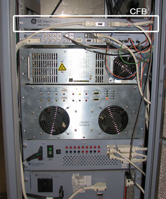
This procedure details the CAN fiber-optic board (CFB) replacement steps. The CFB is located in the PEN cabinet.
CFB Removal
Procedure
- Remove the front cables to the CFB.
Figure 2. Front of CFB 
- Note:Using a ¼ inch wrench, remove the four screws that secure the protective cover.
If you need better access to the CFB, unscrew the two thumbscrews on the front of the CFB panel. Carefully slide the shelf forward, taking care with surrounding cords, to perform the CFB replacement.
Figure 3. CFB Panel Thumbscrews 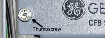
Figure 4. Protective Cover Screw Locations 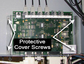
- Disconnect the fiber optic lines from connectors J1 through
J7.
Figure 5. CFB Fiber Optic Line Locations 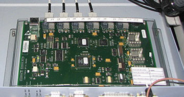
Fiber Optic Repeater Board Installation
Procedure
Finalization
Procedure
- Remove LOTO from the system and restore all power. See the MR Service Safety Manual, PN 5452735.
- Perform CFB Functional Diagnostics.