
- 00000018WIA30D30130GYZ
- id_123749411.1
- Jul 5, 2019 10:03:33 PM
Power Equipment Monitor (PEM) Replacement
Prerequisites
| Required persons | Preliminary requirements | Procedure | Finalization |
|---|---|---|---|
| 1 | Not Applicable | 30 minutes | Not Applicable |
| Item | Quantity | Effectivity | Part number | Manufacturer |
|---|---|---|---|---|
| Non-Magnetic Tool Kit (or equivalent) | 1 | - |
5113258 | - |
| Item | Quantity | Effectivity | Part number | Manufacturer |
|---|---|---|---|---|
| Tie Wraps | 2 | - | - | - |
| Item | Quantity | Effectivity | Part number | Manufacturer |
|---|---|---|---|---|
| Power Equipment Monitor (PEM) Chassis | 1 | - |
See FRU manual | - |
| Condition | Reference | Effectivity |
|---|---|---|
|
PDU must be powered off. | - | - |
Procedure
- Disconnect the cables on the front of the PEM chassis.
Figure 1. PEM Chassis 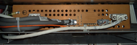
- Remove the four screws holding the PEM chassis (two on each
side).
Figure 2. Mounting Screws 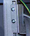
- After removing the PEM chassis from the PGR cabinet, remove
the module from the shelf by removing the 4 nuts.
Figure 3. Nuts on Shelf for PEM Chassis 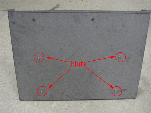
- Secure the leak sensor cable and the PEM board IF cable with
a cable tie through the right anchor on the front of the PEM chassis
platform. Then secure the leak sensor cable, PEM board IF cable, PEM
board fan tray cable, and 48V PDU-PEM board cable with a second wire
tie through the left anchor.
Figure 4. PEM Chassis Wire Tie Anchors 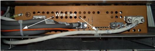
Finalization
- Remove LOTO from the PDU. See the MR Service Safety Manual, PN 5452735.
- Perform a TPS reset and review the error log for any PEM chassis faults.
- Perform a verification scan with the DQA phantom.