Installs the hydraulic cylinder in a dockable patient table.
Procedure
Replace the collar and pin on the hydraulic cylinder so it is flush at both ends.
Replace the washer and screw on the new cylinder.
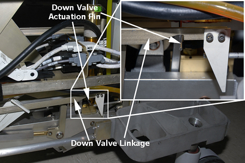
Prepare the replacement cylinder for installation by pressing the cylinder to its fully retracted position. (It may be necessary to move the linkage to fit the actuation pin of the down valve into the groove of the linkage.)
Figure 1. Down valve actuation pin
Carefully angle the bottom of the hydraulic cylinder into the base of the table to avoid bending the actuation pin on the down valve.
Insert the cylinder mounting pin to secure the base of the hydraulic cylinder to the frame of the table and reattach the e-clip.
Reattach the up sensor bracket.
Reconnect the hydraulic lines to the base of the hydraulic cylinder.
Hold the down valve open and exercise the up pump foot pedal to bleed the hydraulic system by shunting air to the hydraulic reservoir.
If the cradle is still attached to the table, release the cradle and manually slide it forward to access the table top adjustment screw hole.
Align the upper cylinder shaft with collar (hole) in the bottom of the table, then slowly pump up the cylinder until the table raises slightly; guide the up sensor bracket into position.
Note: If available, a second person can assist by pumping the table up while the first person ensures that the top of the cylinder shaft moves into the collar (hole in bottom of table)
.
When top of cylinder reaches table top, reattach the e-clip.
Make sure the lock safety bar is in the vertical (up) position.
Partially open the bleed screw on the hydraulic cylinder until no air bubbles are visible.
Open the down valve and lower the table to its lowest position.
When the table is fully up, bleed the cylinder again by partially opening the bleed screw until no air bubbles are visible.
Notice
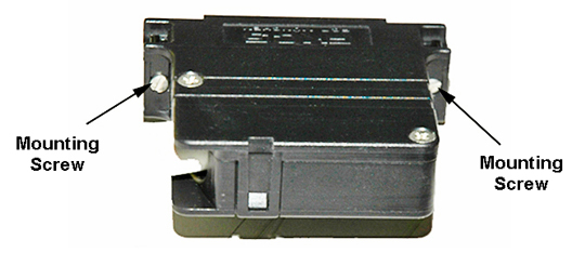
When reconnecting the large J1/J2 and J4/J5 black cable connectors, their lightweight aluminum screws can be easily stripped. Do not over torque when replacing the cable connectors on the TIP, and avoid overtightening the screws shown below.
If a TIP is present, reconnect all cable connectors to the front side of the TIP as shown in Figure 4, and replace both TIP screws on each side.
Figure 2. Black cable connector screws
Put the upper bellows in the down position, and replace both lower base side and front base covers.
Replace the cover plug on the table top, then replace the cradle assembly.