
- 00000018WIA3008BE20GYZ
- id_131058183.0
- Aug 29, 2019 1:57:42 AM
Cradle Assembly Removal and Replacement
Prerequisites
| Required persons | Preliminary requirements | Procedure | Finalization |
|---|---|---|---|
| 1 | Not Applicable | See Procedure Overview minutes | Not Applicable |
| Item | Quantity | Effectivity | Part number | Manufacturer |
|---|---|---|---|---|
| Non-ferrous tool kit | 1 | - |
5113258 or 5112581 | - |
| Wood blocks or similar non-ferrous material for propping up cradle | As needed | - |
N/A | - |
| Item | Quantity | Effectivity | Part number | Manufacturer |
|---|---|---|---|---|
| Loctite 242 | 0.5 CC | - |
46-170686P1 | - |
| Item | Quantity | Effectivity | Part number | Manufacturer |
|---|---|---|---|---|
| 16-Channel Cradle Assembly, non-electrical | N/A | Curved non-electrical table |
See FRU Manual | - |
| Rear Subcomponents (Mark #) | As listed below | Flat table | - | - |
| • P-Port Cover (48) | 1 | - |
See FRU Manual | - |
| • Connecting Rod Block (38) | 1 | - |
See FRU Manual | - |
| • Handle Bar (30) | 1 | - |
See FRU Manual | - |
| • Connecting Block (32) | 1 | - |
See FRU Manual | - |
| • Bell Crank (33) | 1 | - |
See FRU Manual | - |
| • Support (34) | 1 | - |
See FRU Manual | - |
| • Hexagon Socket Head Shoulder Screw (53) | 1 | - |
See FRU Manual | - |
| • Handle Cover (16) | 1 | - |
See FRU Manual | - |
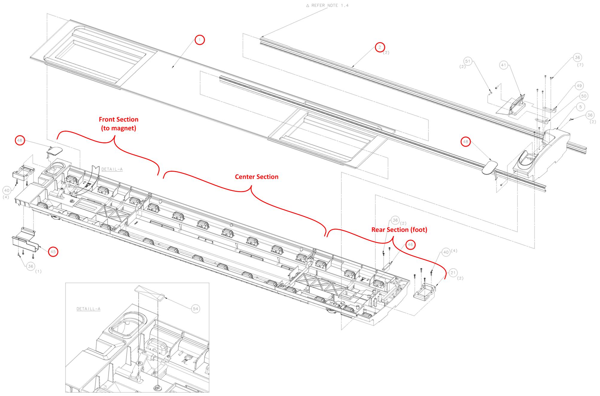
| Front Subcomponents (Mark #) | As listed below | Flat table | - | - |
| • Front Cable Shield (45) | 1 | - |
See FRU Manual | - |
| Center Subcomponents (Mark #) | As listed below | Flat table | - | - |
| • Front Section (3) | 1 | - |
See FRU Manual | - |
| • Rear Section (4) | 1 | - |
See FRU Manual | - |
| • Cotton Rod (22, 23) | 2 | - |
See FRU Manual | - |
| • Connecting Rod Block (38) | 1 | - |
See FRU Manual | - |
| • Release Bar (24) | 1 | - |
See FRU Manual | - |
| • Rod Cap (13) | 1 | - |
See FRU Manual | - |
About this task
Procedure Timing (minutes):
- Non-electrical table: 15
- 32-channel curved table: 30
- 32-channel flat table: 125
Not all tables are valid on all systems.
Choose the correct procedure for the type of table you are servicing:
- Non-electrical table: Removing Cradle from Curved Non-Electrical Patient Table
-
32-channel flat table: Removing Cradle from Flat Table, Replacing Rear Cradle Components, Replacing Front Cradle Components, Replacing Center Cradle Components, Replacing P-Port Covers
Removing Cradle from Curved Non-Electrical Patient Table
About this task
Procedure
- At the same time, press the cradle latch block and push in the cradle release button at the front of the cradle.
Figure 2. Cradle removal 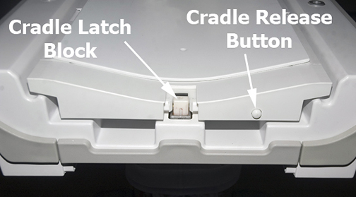
Push in the right actuator on the table front base.CAUTION 
Figure 3. Table Front Base 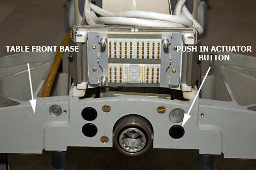
- Note: Pressing the actuator button engages the secondary cradle latch cable and causes the pin stop to move down flush with the table top surface, allowing the cradle to slide forward.Prop up the cradle or remove the cradle from the patient table to perform desired maintenance.
Figure 4. Propping Up Front of Cradle 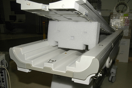
Removing Cradle from Flat Table
About this task
Procedure
- At the same time, press the cradle latch block and push in the cradle release button at the front of the cradle.
Figure 5. Cradle Removal
Push in the right actuator on the table front base.CAUTION Figure 6. Table Front Base Note: Pressing the actuator button engages the secondary cradle latch cable and causes the pin stop to move down flush with the table top surface, allowing the cradle to slide forward.- Remove the cradle in part or in full, as needed:
- If you do not need to fully remove the cradle, follow these steps.
- Slide the cradle forward far enough to clear the cradle guide rail latches at the rear of the table.
- Use wood blocks (or similar) to prop up the front of the cradle.
Figure 7. Propping up Front of Cradle
- If you need to fully remove the cradle, follow these steps.
-
Remove the cradle cover and then the PA coil or PA filler. See GEM Replacements and follow the steps for PA coil removal.
Note: Do not follow instructions for reinstalling a PA coil or PA filler at this time. -
Remove the mid ribs over the P2 cable.
Figure 8. Cradle Mid Ribs 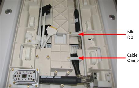
-
Disconnect the cotton rod attachment.
Figure 9. Cotton Rod Attachment Disconnected 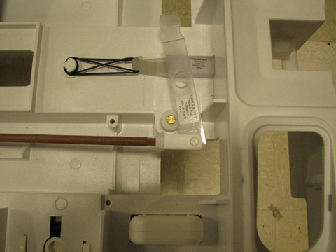
-
Release the cradle.
-
Move the cradle out from the table far enough to expose the bottom cover (front cable shield) beneath the P2 connector.
-
Detach the P-port base before disconnecting the P connector. Make note of how the P-port base is oriented.
Figure 10. P-Port Attached to Base 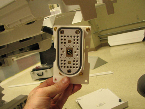
-
Remove the front cable shield.
-
Disconnect the two P-port connectors from the cradle and remove all cable clamps.
-
Use wood blocks (or similar) to prop up the rear end of the cradle.
-
Disconnect the two cable tracks from the bottom of the cradle.
-
Carefully feed the cables and connectors through the holes located at the rear of the cradle and remove the cradle from the table.
-
- To replace the cradle, perform these steps:
-
Position the cradle on the table and carefully feed the cables and connectors through the holes located at the rear of the cradle.
-
Reinstall the cable tracks at the bottom of the cradle.
-
Route the cabling as shown below.
Figure 11. P2 Cable Routing 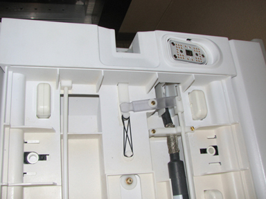
Figure 12. Final PA Coil Cable Routing 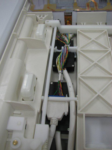
Figure 13. P4 Cable Routing 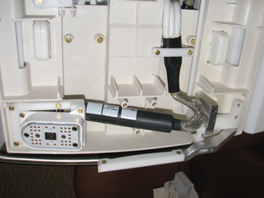
-
Replace all cable clamps and reconnect the two P-port connectors on the cradle.
-
Replace the front cable shield.
-
Replace the mid ribs over the P2 cable.
-
Reinstall the PA coil or PA filler. See GEM Replacements and follow the steps for PA coil installation.
-
Replace the cradle cover.
-
- If you do not need to fully remove the cradle, follow these steps.
Replacing Rear Cradle Components
Procedure
- Remove the cradle release cover.
Figure 14. GEM Cradle Release Cover 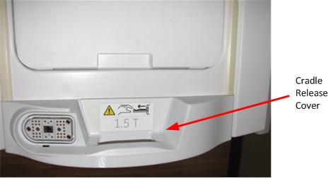
- Remove the screws on the side of the rear section and lower the cradle back onto the table.
Figure 15. Cradle Rear Screws 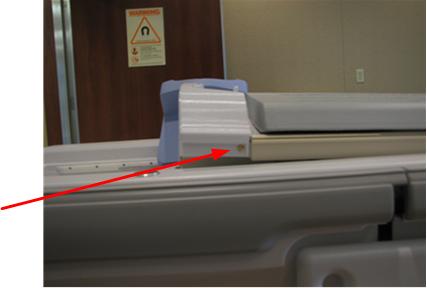
- Remove the three screws holding the rear section cover to the cradle.
Figure 16. Screws Holding Rear Section Cover 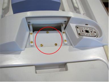
- Remove the upper screw for each cover mounting block and rotate out of the way.
Figure 17. Mounting Blocks Rotated 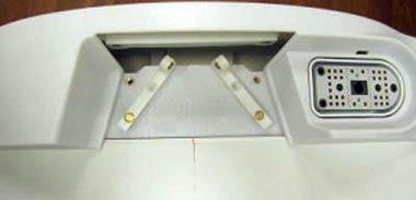
Replacing Front Cradle Components
Procedure
- Release the cradle and slide the cradle off the table approximately 6 inches (100 mm) to expose the cradle front.
- Refer to the cradle assembly drawing to replace any of the front subcomponents in the Replacement Parts list.
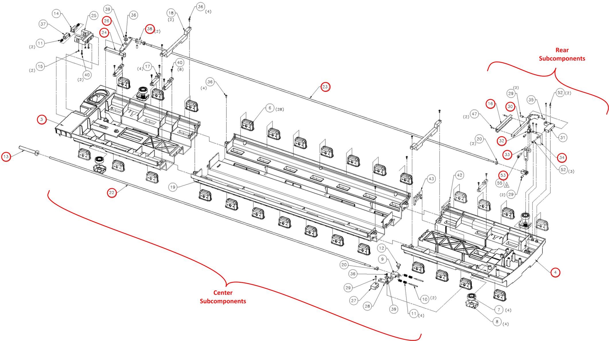
Replacing Center Cradle Components
Procedure
Replacing P-Port Covers
Procedure
- Each P-port cover (front and rear) is attached by a rubber tether. Remove the P-port cover by gently tugging its tether to pull it out.
- Replace with a new P-port cover, gently pushing its rubber tether into place.
Finalization
Procedure
- Dock the table.
- Confirm that the cradle release functions properly.
- Confirm that the LPCA connects to the cradle and that the cradle can move into the bore.
- If the cradle includes a PA coil, perform an MCQA scan. See GEM MCQA Setup - PA Lower.