
- 00000018WIA30C20130GYZ
- id_123737981.9
- Oct 7, 2020 10:43:15 AM
Patient Table Up Limit Replacements
Prerequisites
| Required persons | Preliminary requirements | Procedure | Finalization |
|---|---|---|---|
| 1 | Not Applicable | 30-120 minutes | 15-30 minutes |
| Item | Quantity | Effectivity | Part number | Manufacturer |
|---|---|---|---|---|
| 5/16 hex bit (3/8 drive) | 1 | - | - | - |
| Non-ferrous Tool Kit | 1 | - |
5112581 | - |
| Torque Wrench, 8-50 N m Adjustable, non-magnetic | 1 | - |
5534134 or 5534134-2 | - |
| Item | Quantity | Effectivity | Part number | Manufacturer |
|---|---|---|---|---|
| Loctite 242 | As needed | - |
See FRU Manual | - |
| Item | Quantity | Effectivity | Part number | Manufacturer |
|---|---|---|---|---|
| Up Sensor Cable | 1 | - |
See FRU Manual | - |
| Up Sensor Cable Tubing | 1 | - |
See FRU Manual | - |
| Up Sensor Top Bracket | 1 | - |
See FRU Manual | - |
| Up Sensor Cable | 1 | Curved table |
See FRU Manual | - |
| Up Sensor Cable Tubing | 1 | Curved table |
See FRU Manual | - |
| Up Sensor Top Bracket | 1 | Curved table |
See FRU Manual | - |
| Up Limit Switch Mounting Bracket | 1 | Flat table |
See FRU Manual | - |
| Up Limit Switch Adjuster Block | 1 | Flat table |
See FRU Manual | - |
| Up Limit Switch Link | 1 | Flat table |
See FRU Manual | - |
| Backing Plate with Brass Anchor | 1 | - |
See FRU Manual | - |
About this task
Overview
The patient table up limit switch components are used to set the hydraulic cylinder upper limit. This procedure explains how to replace the patient table up limit switch components.
There are two possible configurations for the table up limit – cable or hook (switch). Follow the instructions for the type of table you are servicing.
The up limit switch mounting bracket for an electrical table requires two persons and the timing varies depending on whether the cradle is removed or not.
See each procedure for specific timing and number of required persons.
Up Sensor Cable and Tubing Replacement (Curved Table Only)
About this task
Required Persons: 1. Procedure Timing: 30 minutes.
Procedure
Lower the table lock safety bar.Warning 
Figure 1. Table Lock Safety Bar 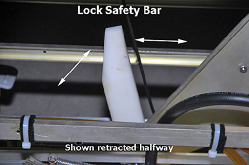
- Remove the hair pin and retaining pin securing the bottom end
of the cable to the bell crank.
Figure 2. Pin and Hair Pin 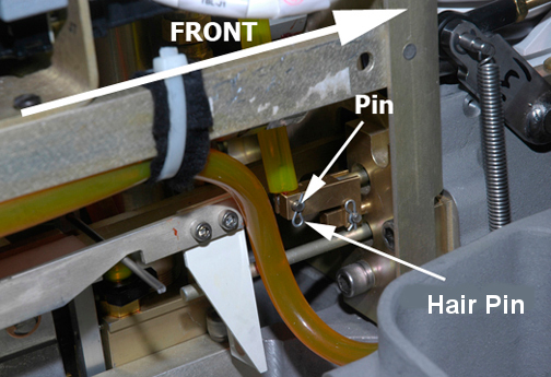
- Remove the clamp securing the cable to the up sensor top bracket.
Figure 3. Table Up Limit Cable Replacement 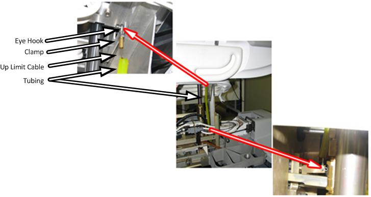
- Adjust the table up limit cable so that the plunger can move
1 to 2 mm when the hydraulic cylinder is fully extended.
If the cable is too loose, the plunger will not engage the dock switch fully and the system will not recognize that the table is fully up.
If the cable is too tight, the cable may break.
Figure 4. Table Dock Push Button 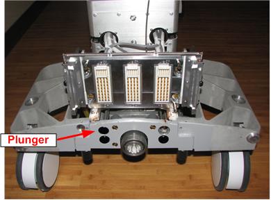
Up Sensor Top Bracket Replacement (Curved Table Only)
About this task
Required Persons: 2. Procedure Timing: 90 minutes.
Procedure
Lower the table lock safety bar.Warning Figure 5. Table Lock Safety Bar - While moving the table down rod to the rear of the table, pull
down on the hydraulic shaft. Stop when the hydraulic shaft is low
enough to access the top of the up sensor top bracket.
Figure 6. Hydraulic Shaft 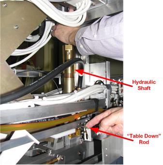
Up Limit Switch Link Replacement (Flat Table Only)
About this task
Required Persons: 1. Procedure Timing: 30 minutes.
Procedure
Lower the table lock safety bar.Warning Figure 7. Table Lock Safety Bar - Remove the outer hair pin holding the link to the bell crank.
Figure 8. Hair Pins - Link to Bell Crank 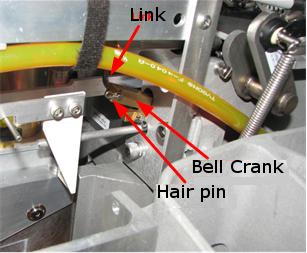
Up Limit Switch Adjuster Block Replacement (Flat Tables Only)
About this task
Required Persons: 1. Procedure Timing: 30 minutes.
Procedure
- Remove the two screws holding the adjuster block to the mounting
bracket.
Figure 9. Screws Holding Adjuster Block 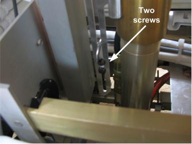
Up Limit Switch Mounting Bracket Replacement
About this task
Required Persons: 2. Procedure Timing: 120 minutes.
Procedure
- While moving the table down rod to the rear of the table, pull
down on the hydraulic shaft. Stop when the hydraulic shaft is low
enough to access the top of the up limit switch mounting bracket.
Figure 10. Hydraulic Shaft
Up Limit Link Mechanism Anchor Replacement (Flat Table Only)
About this task
Required Persons: 1. Procedure Timing: 30 minutes.
Procedure
Lower the table lock safety bar.Warning Figure 11. Table Lock Safety Bar - Remove e-clip and washer from table down rod. Slide table down rod from patient table.
Figure 12. E-clip and Washer 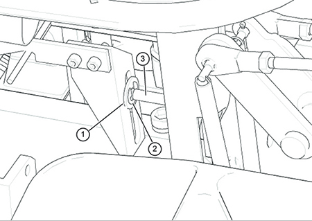
ITEM DESCRIPTION 1 Washer 2 E-clip 3 Table Down Rod - Remove hair pin from bell crank. Remove pin to remove cable or hook.
Figure 13. Backing Plate 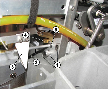
ITEM DESCRIPTION 1 Screws with lockwashers 2 Table down rod 3 Down bracket 4 Brass anchor 5 Hair pin
Finalization
Procedure
- Verify proper operation of the table.
- Raise the table lock safety bar.
- Dock the table.
- Verify proper up/down table motion.
- When the table is in a fully raised position, verify that the cradle and LPCA can be advanced normally into the bore.
- Verify that raising the table to its full height results in the LPCA automatically driving out to engage the cradle.
- Verify that lowering the table results in automatic retraction of the LPCA into the bridge.
- Verify normal cradle and LPCA motion from the home position to end of travel on the bridge using enclosure In Fast and Out Fast buttons at the operator console.
- Replace the upper bellows and lower base covers, and the front base cover.