
- 00000018WIA30200130GYZ
- id_123739271.17
- Aug 5, 2020 10:12:57 AM
Patient Table Cable Take-up and GEM MUX Box Replacement
Prerequisites
| Required persons | Preliminary requirements | Procedure | Finalization |
|---|---|---|---|
| 1 | Not Applicable | 120 minutes for any non-GEM cable track; 120 minutes for P3 ODU to MUX (GEM only); 400 minutes for PA to MUX (GEM only); 220 minutes for P2 or P4 (GEM only) | Not Applicable |
| Item | Quantity | Effectivity | Part number | Manufacturer |
|---|---|---|---|---|
| Phillips screwdriver | 1 | - | - | - |
| Flat head screwdriver | 1 | - | - | - |
| Standard Allen wrench set | 1 | - | - | - |
| Small flat head screwdriver with long shaft | 1 | - | - | - |
| Pliers | 1 | - | - | - |
| 2 x 4 x 10 in (5 x 10 x 25 cm) block of wood (or similar non-ferrous material) | 2 | - | - | - |
| Standard wrench set | 1 | - | - | - |
| Non-ferrous Phillips screwdriver | 1 | - | - | - |
| MCRv Tool Kit (1.5T) | 1 | - |
5182417 | - |
| Item | Quantity | Effectivity | Part number | Manufacturer |
|---|---|---|---|---|
| Loctite 242 | 0.5 cc | - |
46-170686P1 | - |
| Material handling gloves | 1 pair | - | - | - |
| Item | Quantity | Effectivity | Part number | Manufacturer |
|---|---|---|---|---|
| 1.5T PA MUX Box Assembly with Cable (PA to MUX) | 1 | - |
See FRU Manual | - |
| 1.5T Touch & Go PA GEM Coil Table Harness (P3 ODU to MUX) | 1 | - |
See FRU Manual | - |
| 1.5T P2 Table Side Docking Connector with Replacement Track Lids (P2 ODU to P2) | 1 | - |
See FRU Manual | - |
| 1.5T P4 Table Side Docking Connector with Replacement Track Lids (P4 ODU to P4) | 1 | - |
See FRU Manual | - |
| ||||||||
About this task
Overview
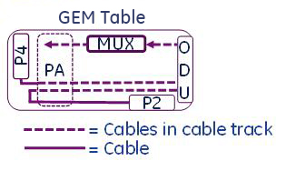
The GEM table has P2, P3 (hidden), and P4 port connectors in the table.
This procedure describes the replacement of the patient table cable take-up from:
-
The P-port connection to the table ODU connector
-
The PA coil to the multiplexer (MUX)
-
The MUX to the ODU connector
The new rev tables introduced in 2017 come with an additional line from the P-ports through the cable track assembly, Mux and then to the Dock connector. This additional line is used only on systems that have the MEMS power supply (systems that have DPP receivers).
The Cable Track Assembly FRU will automatically change up to the one that supports the MEMS Table as and when the Legacy part stock goes down.
The legacy cable track assembly should not be replaced on a table that supports MEMS.
The MUX Box FRU will also change to support the MEMS feature.
This instruction contains the following procedures:
Replacing P2 or P4 Patient Table Cable Take-Up for GEM Table With or Without MEMS Support
Procedure
- Remove both lower base side covers and fasten the upper bellows in the up position. See Patient Table Upper Bellows and Lower Base Side Cover Removal.
Figure 2. Patient Table Covers 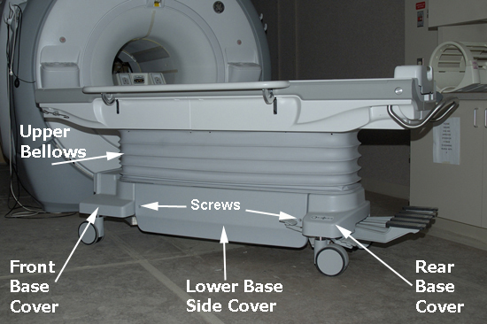
Lower the table lock safety bar, then lower the table and verify that its weight is resting on the safety bar.Warning Figure 3. Table Lock Safety Bar 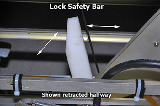
- Remove the bottom front cover, located on the front underside of the patient table, and the right or left table side cover, depending on which cable track is being removed.Note:
When standing at the foot of the patient table facing the magnet, the P2 and P4 cable take-up are on the right side and P3 cable take-up is on the left side.
Figure 4. Bottom Front Cover 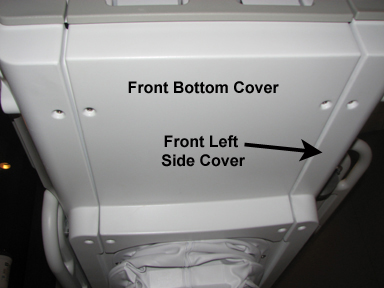
- Disconnect the gray TBL P3-J7 or P4-J7 cable from the Touch and Go connector located in the upper left or right corner inside the table top.
Figure 5. Touch and Go Connector 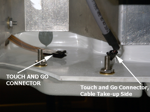
- Manually unlock the cradle and move it forward approximately 24 in (61 cm) to clear the guide rails. See Removing and Replacing Cradle Assembly.
Figure 6. Guide Rail Clearance 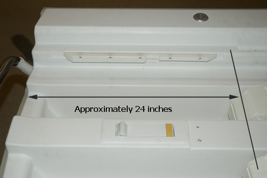
- Locate the rear of the cradle, remove the two inner screws with a Phillips screwdriver, and lift the plastic cradle cover out.
Figure 7. Removing Cradle Cover 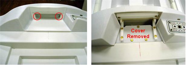
- Remove the three screws on the top of the rear section.
Figure 8. Screws on Rear Section 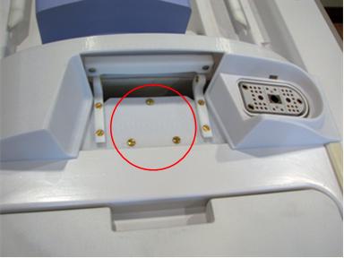
- Remove the upper screw for each cover mounting block, and rotate them out of the way.
Figure 9. Mounting Blocks Rotated 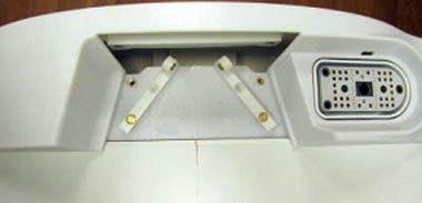
- While wearing gloves, remove the left and right strap rails by sliding each one out from the rear of the cradle. Prop up the rear of the cradle to aid removal.
Figure 10. Table Strap Rails 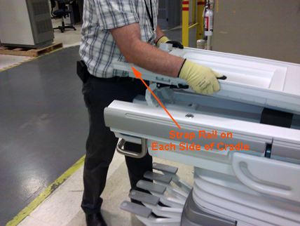
- Remove the shoulder screw and the four screws securing the two end ribs to the cradle (one near the front and one near the rear section of the cradle.)
Figure 11. Removing Shoulder Screw 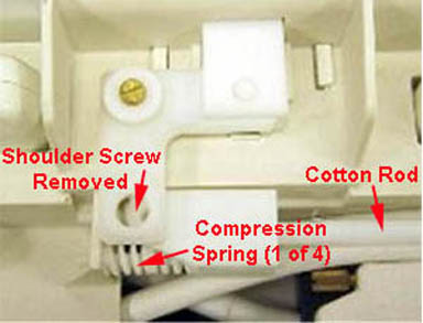
Figure 12. Removing 2 Screws on End Rib 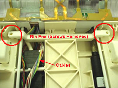
- Remove the six screws from the PA coil or PA filler. Carefully move the filler enough to have clear access to the cotton rod. Be careful not to strain the attached cables while moving the filler.
Figure 13. Removing Screws on PA Coil or Filler 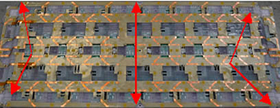
Figure 14. Moving the PA Coil or PA Filler 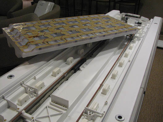
- Remove the cotton rod attachment, and rotate the cotton rod out of the way.
Figure 15. Cotton Rod and Cotton Rod Attachment 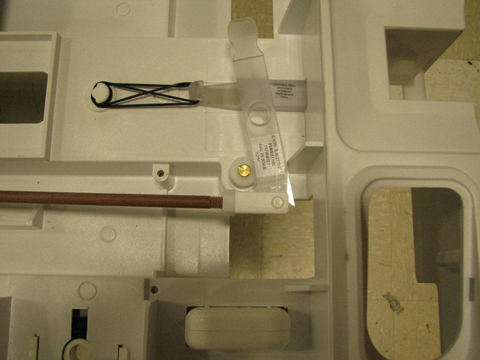
- Remove the four screws on the cable grommet and pull the cables to the side.
Figure 16. Table Cable Grommet 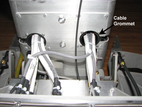 Note:
Note:If changing P2, both cable grommets must be removed.
- Replace the cable by following the above steps in reverse order.
Figure 17. Table Cable Track Wiring 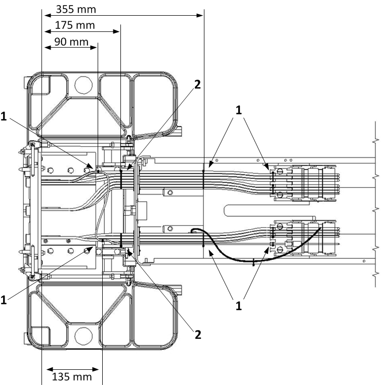
1 When installing these cable ties, ensure that the knot end faces UP. 2 When installing these cable ties, ensure that the knot end faces DOWN. Apply the cable ties at the locations indicated in Figure 17.
Replacing GEM Table PA Multiplexer Box Assembly
Procedure
- If removing the P3 (PA coil) cable track on the left side, disconnect the cables from the table multiplexer found on the left side of the table.
Figure 18. Table Multiplexer Located in Front Upper Left Corner 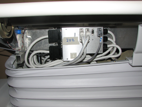
- Reverse the steps above to install the new cable track. See Figure 20 for cable tie locations.
Figure 19. Final Cradle Cable Routing 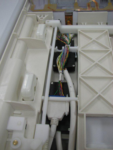
Figure 20. Cable Tie Locations 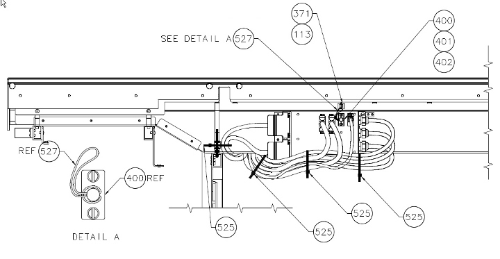
Replacing GEM Table P3 ODU to PA Multiplexer
Procedure
- Remove the left lower base side cover, and fasten the upper bellows in the up position. See Patient Table Upper Bellows and Lower Base Side Cover Removal.
Figure 21. Patient Table Covers
Lower the table lock safety bar, then lower the table and verify that its weight is resting on the safety bar.Warning Figure 22. Table Lock Safety Bar - Remove the screws holding the bottom of the cable track.
Figure 23. Flat (GEM) Table Cable Track Bottom Section 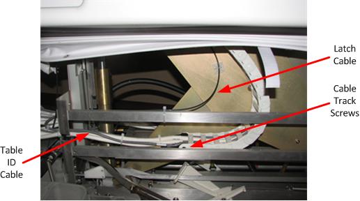
Finalization
Finalization
-
Dock the patient table.
-
Confirm that the cradle release functions properly.
-
Confirm that the LPCA connects to the cradle and the cradle moves into the bore.