
- 00000018WIA30D5EE20GYZ
- id_131071283.0
- Aug 29, 2019 1:58:12 AM
GEM MCQA Setup - PV Left
Prerequisites
| Required persons | Preliminary requirements | Procedure | Finalization |
|---|---|---|---|
| 1 | Not Applicable | 30 minutes | Not Applicable |
The 1.5T GEM Coil MCQA will use the 1.5T phantoms, which are green in color. The 3.0T GEM Coil MCQA will use the 3.0T phantoms, which are pink in color. The Small Cylindrical Unified Phantom is green in color and for both 1.5T and 3.0T coils.
Note:
Coils do not ship with phantoms. Phantoms come in a Unified Phantom set with the MR System.
| Item | Quantity | Effectivity | Part number | Manufacturer |
|---|---|---|---|---|
| TL Unified Phantom (For 1.5T) | 2 | - |
5343347 | - |
| Large Cylindrical Unified Phantom (For 1.5T) | 1 | - |
5342679 | - |
| TL Unified Phantom (For 3.0T) | 2 | - |
5343347-2 | - |
| Large Cylindrical Unified Phantom (For 3.0T) | 1 | - |
5342679-2 | - |
| Small Cylindrical Unified Phantom (For 1.5T and 3.0T) | 1 | - |
5342680 | - |
| PA Phantom Positioner (For 1.5T and 3.0T) | 1 | - |
5405748 | - |
| PV Phantom Positioner (For 1.5T and 3.0T) | 1 | - |
5405749 | - |
Procedure
- Place the Flat Filler Panel (shown below) on the GEM table.
Figure 1. Flat Filler Panel 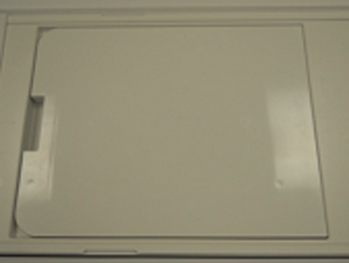
- Place the two TL Unified Phantoms on the GEM table (center the
phantoms in RL direction), and ensure the top edge (facing the bore)
of the first phantom coincides with the edge of the Flat Filler Panel.
Figure 2. Placement of TL Unified Phantoms 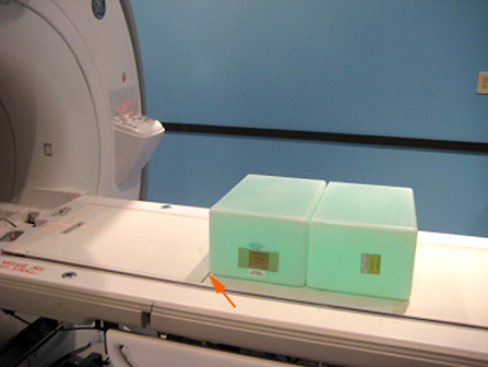
- Place the PV Coil on top of the Flat Filler Panel, making sure
the edge of PV Coil touches the edge of the TL Unified Phantom as
shown.
Figure 3. Edges of PV Coil and TL Unified Phantom 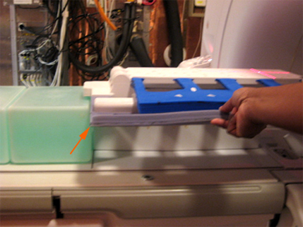
- Place the PA Phantom Positioner on top of the TL Unified Phantoms,
fitting the alignment block on the PV Coil into the alignment notch
on the PA Phantom Positioner as shown.
Figure 4. Placement of PA Phantom Positioner 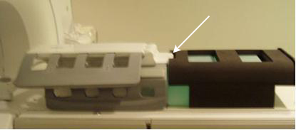
- Flip the PV Upper unit onto the PA Phantom Positioner, and fasten
with Velcro® straps as shown.
Figure 5. Placement of PV Upper Unit on Phantom Positioner 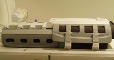
- Place the Large and Small Unified Cylindrical Phantoms into
the PV Phantom Positioner, and place the phantom assembly under the
left side of the PV Coil.Note:
Make sure the edge of the Large Unified Cylindrical Phantom is aligned with the edge of the TL Unified Phantom. Wrap the left portion of the PV Coil closely around the phantom assembly.
Figure 6. Placement of Large and Small Cylindrical Phantoms into Positioner 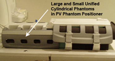
- Connect the PV Coil to Port P2 on the GEM table, landmark the
coil in the middle of the latch (shown below) of the PV Coil, and
press Advance to Scan.
Figure 7. Latch on PV Coil 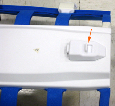
- Run the Multi-Coil Quality Assurance Tool. Ensure that the correct coil is selected in the Current Coil field: 1.5T_GEM_PV_Left (shown below) or
3.0T_GEM_PV_Left for a 3.0T system.
Figure 8. MCQA Tool Menu 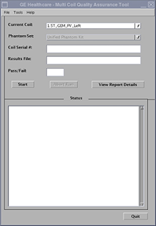
Finalization
No finalization steps.