- 00000018WIA30F8B030GYZ
- id_123739761.5
- Sep 2, 2020 12:56:33 PM
GEM Coil Troubleshooting
Basic GEM PA Coil Theory
For systems with an RF Hub, multicoil bias is supplied on each of the receive lines from each of the RF Switch Board P1 and P2 connectors. This bias is used to enable and disable the various PA coil element receive arrays. The MC bias flows from the RF Switch Boards and through the MUX Module. The MC bias is not switched inside the MUX Module. The MC bias is bypassed around the switching circuitry inside the MUX Module and passes through the J1-PA, J2-PA, and J3-PA connections directly to the PA Coil. Likewise, with the exception of MUX select bits 1-4 which control the MUX switching array and +10VDC Auxiliary Power lines which supply power to the MUX Module switching array, the remaining Coil ID, TX Enable, and Coil Present lines from the RF Control Board pass directly through the MUX Module and to the PA Coil through the J4-PA connection.
RF receive signals from the patient or phantom are detected by the selected PA Coil elements and then routed through the J1-PA, J2-PA, and J3-PA connections to the MUX Module. RF switching circuits inside the MUX Module route the signals onto the proper receive channels to the RF Switch Boards inside the RF Hub. The configuration of the RF switching circuits inside the MUX Module is controlled by the binary setting of the MUX Select bits 1-4.
PA Coil Troubleshooting Hints and Tips
-
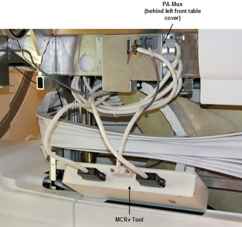
Use Coil Datapath Diagnostic (CDD), which uses MCRv Tool, to troubleshoot PA coil multi-coil bias and coil signal problems. MCRv Tool can be attached to cabling that normally connects to MUX Module inside patient table. See Figure 2. This setup and usage of MCRv Tool is discussed in more detail in CDD service methods document.
-
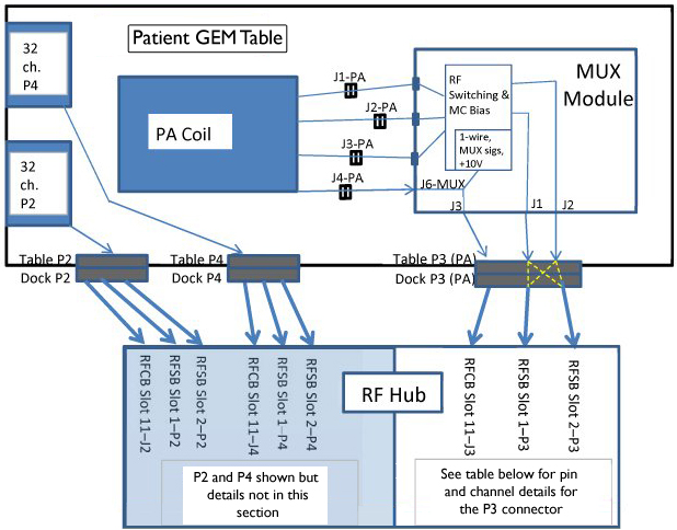
Figure 1 shows interconnections between PA coil and RFSB and RFCB inside RF Hub and how it can be used to check continuity of cables, however, this is often done more quickly and thoroughly by using CDD.
-
Troubleshoot P3(PA) multi-coil bias short-circuit faults by doing these things:
-
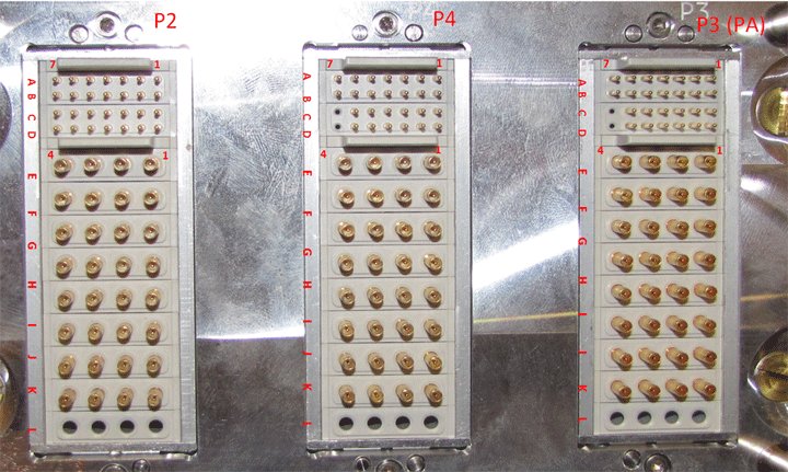
Inspect electrical P3 (PA) connector on patient table and dock for damaged pins.
-
Remove receive line where fault reported or all lines and observe that short- circuit fault is no longer reported. Repeat at every junction in chain until fault isolated.
-
Use CDD and MCRv to help isolate fault location. See CDD service methods document.
-
-
Troubleshoot P3(PA) multi-coil bias open-circuit faults by doing these things:
-
Inspect electrical P3(PA) connector and patient table and dock for damaged pins.
-
Open cradle and reseat 3 PA coil cable connections and watch for recessed/pushed receive line connections.
-
Use CDD and MCRv to help isolate fault location. See CDD service methods document.
-
-
PA Filler assembly can be installed in place of PA coil during troubleshooting and to permit customer scanning using coils other than PA coil. PA Filler contains only a Coil ID chip but does not contain any coil elements and does not require or use multi-coil bias.
-
Multi-coil bias passes around the switching circuitry inside the MUX Module. It is not switched inside the MUX Module. It therefore stands to reason that multi-coil bias failures are unlikely to be due to MUX Module. These failures are more likely result of connector, cabling or PA coil issues.
Using MCRv (Coil Datapath Diagnostic)
The MCRv Tool can be used to verify that the Receive Chain is functioning correctly from the PA Mux Box output to the RFSB in the Rear Hub. The PA Mux Box and path up to the PA Coil is NOT tested. Cables at J1, J2, and J3 on MUX Module can be disconnected and reattached to MCRv Tool for testing. Coil Datapath Diagnostic (CDD) can then be used to test all signal paths from MCRv Tool back to RF Hub. This eliminates manual "signal chasing" using a DVM and probes. Figure 2 is from CDD service methods document and shows setup using MCRv Tool.
GEM PA Coil Signal Path to RF HUB
Table 1 represents the signal paths from the GEM PA Coil back to the RFSB Board. The table should be used as a reference — the Coil Datapath Diagnostic should be used from Mux back to the RFSB.
This table is also useful for running continuity checks between the PA Coil connectors to the Output of the Mux Box. To do this:
-
Disconnect the Cables from the PA Coil at the PA Coil side.
-
Disconnect the Mux Output Cables from the Mux (J1 and J2).
-
Use a DVM and run a continuity check between the Mux Box and PA coil cables in the cable take-up.
PCX Connectors are internal to Mux. These are listed as Reference only. MUX Box is not intended to be serviced internally.
| RF Channel | DC | Rear Hub | DOCK | MUX | PA Coil | ||||||||||
|---|---|---|---|---|---|---|---|---|---|---|---|---|---|---|---|
| RFSB | Pin# | Connector | Pin# | Connector | PCX Connector | Connector J1-PA | Element 3T | Element 1.5T | |||||||
| 19 | DC19 | Slot 1-P3 | 11 | P3 | G3 | J2 - 3 | J8 | 1 | L38 | L37 | |||||
| 23 | DC23 | Slot 2-P3 | 11 | P3 | K3 | J2 - 7 | J10 | 2 | L36 | L35 | |||||
| 31 | DC31 | Slot 2-P3 | 15 | P3 | L3 | J2 - 15 | J17 | 3 | L34 | L33 | |||||
| 27 | DC27 | Slot 1-P3 | 15 | P3 | H3 | J2 - 11 | J15 | 4 | L32 | L31 | |||||
| N/A | None | None | N/A | N/A | N/A | N/A | J42 | 5 | S2 | S2 | |||||
| 18 | DC18 | Slot 1-P3 | 10 | P3 | G2 | J2 - 2 | J12 | 6 | L21 | L19 | |||||
| 22 | DC22 | Slot 2-P3 | 10 | P3 | K2 | J2 - 6 | J14 | 7 | L18 | L16 | |||||
| 30 | DC30 | Slot 2-P3 | 14 | P3 | L2 | J2 - 14 | J32 | 8 | L15 | L13 | |||||
| 3 | DC3 | Slot 1-P3 | 3 | P3 | E3 | J1 - 3 | J28 | 9 | L30 | L29 | |||||
| 7 | DC7 | Slot 2-P3 | 3 | P3 | I3 | J1 - 7 | J30 | 10 | L28 | L27 | |||||
| 15 | DC15 | Slot 2-P3 | 7 | P3 | J3 | J1 - 15 | J41 | 11 | L26 | L25 | |||||
| 11 | DC11 | Slot 1-P3 | 7 | P3 | F3 | J1 - 11 | J31 | 12 | L24 | L23 | |||||
| 26 | DC26 | Slot 1-P3 | 14 | P3 | H2 | J2 - 10 | J13 | 13 | L12 | L10 | |||||
| 2 | DC2 | Slot 1-P3 | 2 | P3 | E2 | J1 - 2 | J30 | 14 | L9 | L7 | |||||
| 6 | DC6 | Slot 2-P3 | 2 | P3 | I2 | J1 - 6 | J29 | 15 | L6 | L4 | |||||
| 14 | DC14 | Slot 2-P3 | 6 | P3 | J2 | J1 - 14 | J40 | 16 | L3 | L1 | |||||
| J2-PA | |||||||||||||||
| N/A | None | None | N/A | N/A | N/A | N/A | J44 | 1 | L19 | L21 | |||||
| N/A | None | None | N/A | N/A | N/A | N/A | J35 | 2 | L16 | L18 | |||||
| N/A | None | None | N/A | N/A | N/A | N/A | J34 | 3 | L13 | L15 | |||||
| N/A | None | None | N/A | N/A | N/A | N/A | J16 | 4 | L10 | L12 | |||||
| 20 | DC20 | Slot 1-P3 | 12 | P3 | G4 | J2 - 4 | J11 | 5 | L37 | L38 | |||||
| 24 | DC24 | Slot 2-P3 | 12 | P3 | K4 | J2 - 8 | J10 | 6 | L35 | L36 | |||||
| 32 | DC32 | Slot 2-P3 | 16 | P3 | L4 | J2 - 16 | J19 | 7 | L33 | L34 | |||||
| 28 | DC28 | Slot 1-P3 | 16 | P3 | H4 | J2 - 12 | J18 | 8 | L31 | L32 | |||||
| N/A | None | None | N/A | N/A | N/A | N/A | J21 | 9 | L7 | L9 | |||||
| N/A | None | None | N/A | N/A | N/A | N/A | J9 | 10 | L4 | L6 | |||||
| N/A | None | None | N/A | N/A | N/A | N/A | J20 | 11 | L1 | L3 | |||||
| 10 | DC10 | Slot 1-P3 | 6 | P3 | F2 | J1 - 10 | J20 | 12 | S1 | S1 | |||||
| 4 | DC4 | Slot 1-P3 | 4 | P3 | E4 | J1 - 4 | J32 | 13 | L29 | L30 | |||||
| 8 | DC8 | Slot 2-P3 | 4 | P3 | I4 | J1 - 8 | J33 | 14 | L27 | L28 | |||||
| 16 | DC16 | Slot 2-P3 | 8 | P3 | J4 | J1 - 16 | J45 | 15 | L25 | L26 | |||||
| 12 | DC12 | Slot 1-P3 | 8 | P3 | F4 | J1 - 12 | J37 | 16 | L23 | L24 | |||||
| J3-PA | |||||||||||||||
| 17 | DC17 | Slot 1-P3 | 9 | P3 | G1 | J2 - 1 | J22 | 1 | L22 | L22 | |||||
| 21 | DC21 | Slot 2-P3 | 9 | P3 | K1 | J2 - 5 | J38 | 2 | L20 | L20 | |||||
| 29 | DC29 | Slot 2-P3 | 13 | P3 | L1 | J2 - 13 | J36 | 3 | L17 | L17 | |||||
| 25 | DC25 | Slot 1-P3 | 13 | P3 | H1 | J2 - 9 | J23 | 4 | L14 | L14 | |||||
| 1 | DC1 | Slot 1-P3 | 1 | P3 | E1 | J1 - 1 | J24 | 5 | L11 | L11 | |||||
| 5 | DC5 | Slot 2-P3 | 1 | P3 | I1 | J1 - 5 | J25 | 6 | L8 | L8 | |||||
| 13 | DC13 | Slot 2-P3 | 5 | P3 | J1 | J1 - 13 | J46 | 7 | L5 | L5 | |||||
| 9 | DC9 | Slot 1-P3 | 5 | P3 | F1 | J1 - 9 | J39 | 8 | L2 | L2 | |||||
Dark grey cells in the DC column indicate combined elements. These should supply approximately double the MC bias current.