- Optima MR450w BASE 1.5T System Service Methods
- 5690012-2EN Revision 3
- 00000018WIA30AF4450GYZ
- id_20221311.12
- Jun 11, 2021 2:02:50 PM
Removing the pedal link bar connector
Removes the pedal link bar connector that operates the foot pedal.
Prerequisites
| Personnel requirements | |||
|---|---|---|---|
| Required persons | Preliminary requirements | Procedure | Finalization |
| 1 | - | 10 minutes | - |
| Tools and test equipment | |||
|---|---|---|---|
| Item | Quantity | Part number | Manufacturer |
| Nonmagnetic Titanium Service Tool Kit, Small Set | 1 | 5113258 | - |
Procedure
- Remove the two screws that fasten the left and right lower base side covers to the table.
Figure 1. Patient Table Covers (Left Side Shown) 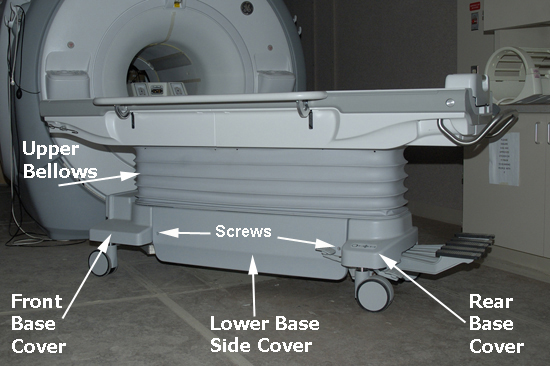
- Remove the four screws (shown below) that secure the rear base cover to the table base and the bellows.
Figure 2. Screws securing rear base cover 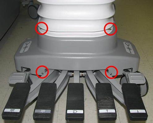
- Lower the table lock safety bar. Lower the table and verify that all weight is resting on the lock bar.
Figure 3. Table Lock Safety Bar 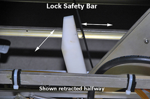
- Remove the spring attached to the pedal link bar connector at the rear of the patient table.
Figure 4. Spring Removal 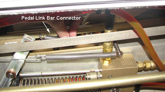
- Remove the E-clip that secures the pedal link bar connector to the pedal that electrically docks the patient table.
Figure 5. Pin Removal from Pedal Link Bar Connector 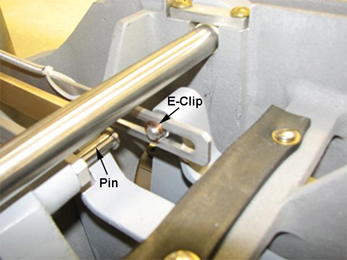
- Pull the link down bar up to allow access to the pedal link bar connector. Push and remove the pin from the pedal link bar connector.
Figure 6. Link down bar 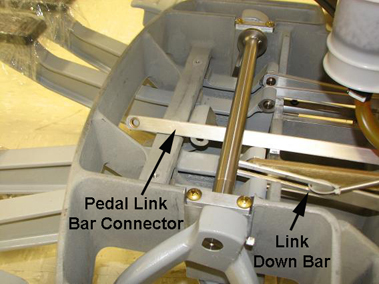
- Move the pedal link bar to access screws on the block lift. Remove the two screws securing the block lift to the pedal link bar connector. Remove the block lift.Note:
Save the two screws and the block lift for installation on the replacement pedal link bar connector.
Figure 7. Block lift on pedal link bar connector 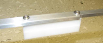
- Disconnect the sensor cable or up limit link.
Figure 8. Sensor cable 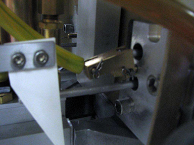
Figure 9. Up limit link 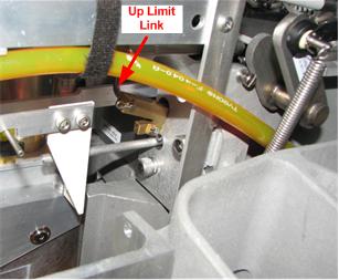
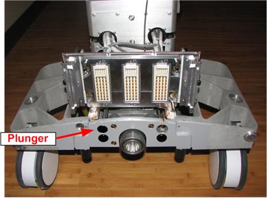
- Push the up-limit rod plunger in to open the hole in the front of the table.
Figure 10. Up limit rod plunger