Ferrous materials can become dangerous projectiles in the presence of the magnetic field that the magnet produces.
Do not bring any ferrous tools or equipment into the magnet room.
CAUTION
Dangerous work area
Use of heavy equipment for coil removal and replacement is a hazard to all personnel in the area.
Set up restricted barriers and signs limiting access to the work area.
Notify all effected personnel in the area prior to starting the service activity.
Review safety procedures and restricted areas for the job.
Wear Personal Protective Equipment (PPE) at all times.
Refer to the Material Handling SRA before starting coil replacement.
Table 6. Required conditions
Condition
Reference
Effectivity
Contact a trained, local body coil tuning expert before starting this procedure, because the coil will need to be tuned as part of the replacement finalization. If necessary, contact the Modality Operations Manager for a list of trained individuals.
-
-
About this task
Use this procedure to replace the RF body coil.
Remove RF body coil
Procedure
Perform LOTO on the PDU/gradient subsystems, XRFD amplifier, and PEN cabinet. See MR Service Safety Manual, PN 5452735.
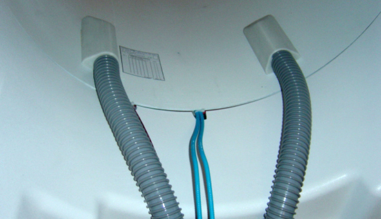
Disconnect the two air hoses at the rear end of the RF body coil.
Disconnect the two drive cables (I and Q) at the rear end of the body coil. Disconnect the DC bias line at the rear, and disconnect the Hart ID cable and DC bias line at the front of the body coil.
Notice: Do not use the air hose manifolds to remove the RF body coil.
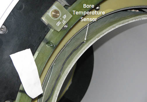
Partially slide out the old RF body coil, and disconnect the bore temperature sensor and tape it to the magnet enclosure so it is out of the way.
Figure 1. Bore temperature sensor cable
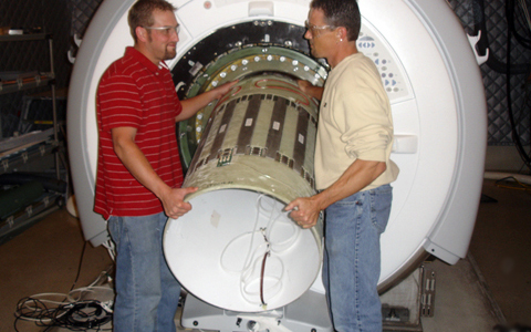
Note: If there is no FRU case available, place the body coil on two pads, making sure they protect the drive cables of the body coil from damage. Make sure the body coil does not roll over.
Fully remove the RF body coil, and place it inside the empty top half of the FRU case.
Figure 2. Removing RF body coil
Install new RF body coil
Procedure
Before installing the RF body coil, attach one of the foam strips at the back bottom edge of the body coil (6 o'clock position where the gradient coil does not have an acoustic barrier).
Slide in the new RF body coil (shown below) with the blue drive cables facing the rear end. Align the mounting pads on the body to the centering strips inside the gradient coil.
Do not use the air hose manifolds to install the RF body coil.
Align the blue drive cables in the rear so the middle of the two drive cables are as close to the 6 o'clock position as visually possible. Make sure the blue drive cables and the DC bias cable are routed through the cutouts on the rear end bell.
Figure 4. Centering RF Body Coil
Reconnect the two air hoses at the rear end of the body coil.
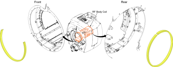
Install the yellow foam as follows:
Front: 2/3 of the diameter, with the top 1/3 open
Rear: Full diameter around body coil
Figure 5. Yellow foam
Replace the front end bell. Refer to Front End Bell Removal and Installation. Confirm that the gap between the front end bell and the RF body coil is 2.5 +/- 0.5 mm with a target/desired gap of 2.0 mm.
Remove LOTO. See the MR Service Safety Manual, PN 5452735.
Finalization
Procedure
Note: RF coil tuning can be done only by personnel who have successfully completed GE Healthcare’s training class for Body Coil Tuning and Stress Test, GEHC-TECH-AMSC-MR5037.
Have the previously contacted, properly trained body coil tuning expert tune the RF body coil.