
- Optima MR450w BASE 1.5T System Service Methods
- 5690012-2EN Revision 3
- 00000018WIA30D12130GYZ
- id_152710582.10
- Nov 17, 2020 12:47:00 AM
RF Amplifier and UPM Calibration
Prerequisites
| Required persons | Preliminary requirements | Procedure | Finalization |
|---|---|---|---|
| 1 | - | 45 minutes (plus 30 minutes for Agilent wattmeter power up) | 5 minutes |
| Item | Quantity | Effectivity | Part number | Manufacturer |
|---|---|---|---|---|
| 12 inch Crescent Wrench | 1 | - | - | - |
| Medium Phillips Screwdriver | 1 | - | - | - |
| Small Flat Head Screwdriver | 1 | - | - | - |
| RF power measurement kit (use one of the following kits): | 1 | - |
EITHER 5307511-2 or 5307511-3 (Bird wattmeter) BOTH 5491202 (Agilent wattmeter) and 5491202-2 (dummy load) | - |
| Digital Multimeter | 1 | - |
46-194427 P284 | - |
| ||||||||||||||||||||
| Condition | Reference | Effectivity |
|---|---|---|
|
Before beginning this procedure, confirm that the exciter has been on for at least 20 minutes. | - | - |
|
When using the Agilent wattmeter, plug in the wattmeter and turn it on. The wattmeter must be powered for at least 30 minutes for stable and accurate readings. | - | - |
About this task
Overview
This procedure provides instruction to set up and calibrate the maximum power for the RF amplifier. The procedure also proceeds through the calibration and functional check of the Universal Power Monitor (UPM) for each channel.
Use the UPM Tool to process each channel through each procedure. For example, when you select head mode, the tool executes the RF amplifier calibration and, if the amplifier passes, proceeds to the UPM calibration and then to the functional check. The process is order-dependent.
Process the body channel first and then the head channel.
RF amplifier and UPM calibration are performed for forward power on a channel. UPM functional check is performed after the channel is calibrated.
The table below describes the calibration steps.
Disabling T/R, DD, and RF Input for Body Mode
Procedure
- On the front of the driver module, disable the TR and DD fault
detection. Set SW2 to TR DISABLE (down) and set SW3 to DD DISABLE
(down).
Figure 1. Driver Module (Front View) Switch 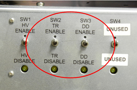 Note:
Note:Leave HV set to ENABLE.
- Set the RF Enable switch on the exciter (located in the top
of the PEN cabinet) to DISABLE (down).
Figure 2. RF ENB Switch in DISABLE (Down) 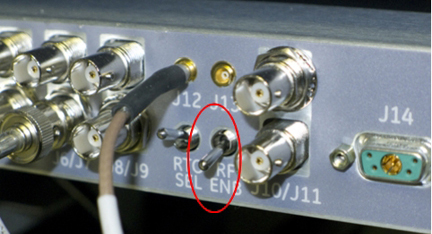
Using Bird Wattmeter and Power Adjustment Kit for RF Body Calibration
Setting up RF Coupler for Body Calibration
Procedure
- Insert the 50 kW element into the Forward sensor port (green
4300A374-2). Lock the element in place using the locking tab on the
sensor. The Reflected port is not used during this procedure. Placing
the 5000 W element (green 4300A374-5) into the Reflected port is just
a safety measure, and is not used during body calibration.
Make sure the arrows on the elements point in opposite directions.
Figure 3. RF Coupler Setup for Body Mode 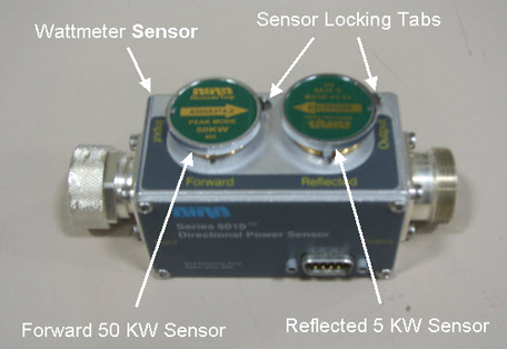
Wattmeter and Dummy Load Setup for Body Channel (XRFD Amplifier)
Procedure
- Connect the input of the coupler to J4 on the front panel of
the RF amplifier.
Figure 4. Connection of RF Coupler to Body Output 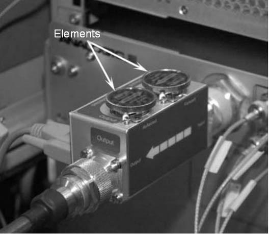
Connect the output of the RF coupler to the dummy load.Warning Figure 5. Complete Body Output Test Setup (16 kW XRFD Amplifier) 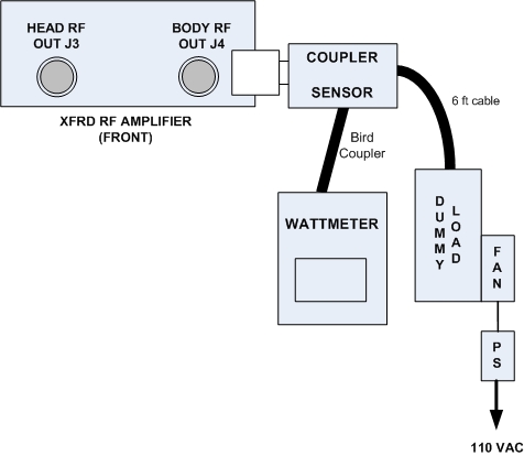
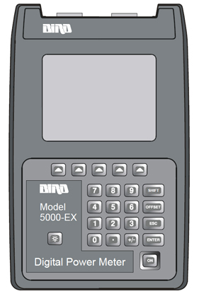
Setting up Bird 5000-EX Wattmeter to Measure Forward Body Maximum Power
About this task
Procedure
- Verify that the output reads 43, and
then press the ENTER button.
Figure 7. Wattmeter Display Set to Read 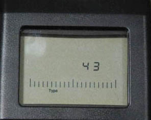
- All kits require an offset to ensure accurate measurement. Locate
the Element Offset Factors card in the kit.
Find the offset for “1.5T Body Output.”
Figure 8. Example Element Offset Factors Card 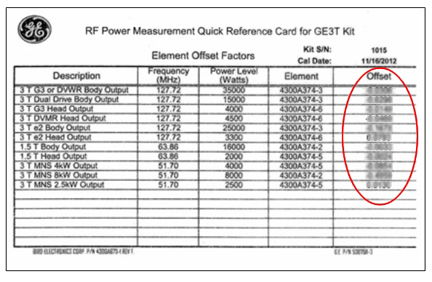
- Press the Offset button on the wattmeter.
Enter the numerical value from the offset card and press the Enter button.Note:
To enter a negative value, first enter the numerical value, then the minus symbol (–).
Figure 9. Wattmeter Set to Display Peak Power 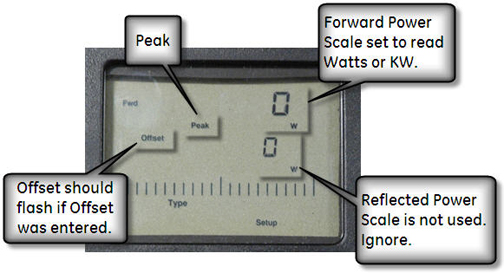
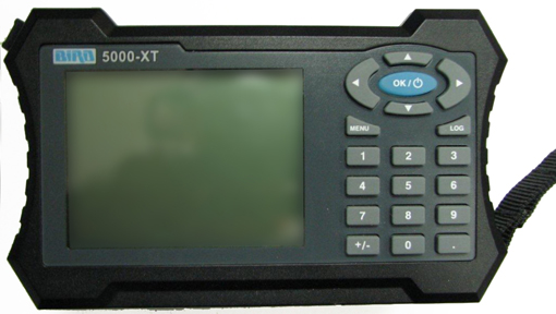
Setting up Bird 5000-XT Wattmeter to Measure Forward Body Maximum Power
About this task
Procedure
- Verify that the output reads 43, and then
press OK.
Figure 11. Wattmeter Set to Read 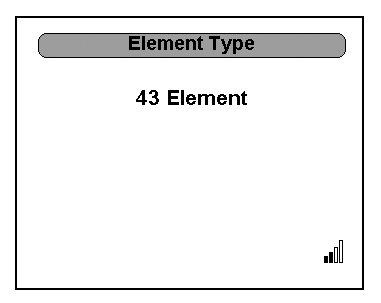
- All kits require an offset to ensure accurate measurement. Locate
the Element Offset Factors card in the kit.
Find the offset for “1.5T Body Output.”
Figure 12. Example Element Offset Factors Card - Press ◄ to return to measurement mode.
Figure 13. Wattmeter Set to Display Peak Power 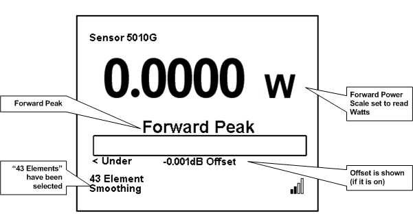
Using Agilent Wattmeter and Power Adjustment Kit for RF Body Calibration
About this task
The Agilent wattmeter must be powered on for at least 30 minutes for stable and accurate readings. Plug in the wattmeter and turn it on at the beginning of this procedure.
Agilent Wattmeter Setup
Procedure
CAUTION
Set up the wattmeter for calibration as shown in the following illustration.Notice - Connect the other end of the sensor probe cable to the Channel A port on the wattmeter.
Figure 14. Agilent Wattmeter Calibration Setup 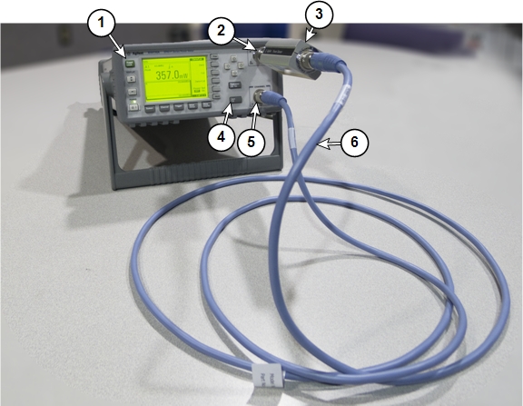
1 Front of wattmeter 4 Zero/Cal button 2 Power reference (PWR REF) port 5 Channel A port 3 Agilent RF power sensor 6 Agilent sensor probe cable
- Connect the other end of the sensor probe cable to the Channel A port on the wattmeter.
Wattmeter and Dummy Load Setup for Body Mode (XRFD Amplifier)
Procedure
DANGER Warning
Verify that the scanner is idle. Confirm that the RF ENB switch on the DTX1 exciter is in the Disable (down) position.Notice - Disconnect the body output cable from J4 one the front panel of the RF amplifier:
- Connect the input of the coupler to J4 on the front panel of the RF amplifier:
Setting up Agilent Wattmeter to Measure Forward Body Maximum Power
Procedure
- Connect the remaining Agilent power components as shown below.
Figure 15. Agilent Power Meter Setup for RF Body Calibration 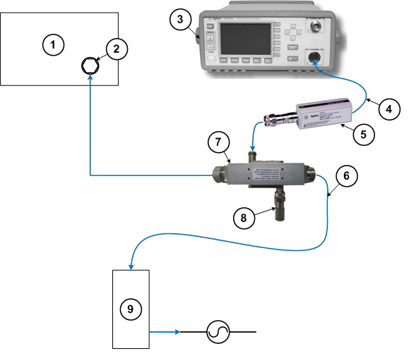
1 RF amplifier (front) 6 RF cable to dummy load 2 RF output port 7 RF coupler 3 Wattmeter 8 Agilent 50 ohm terminator connected to the Reflected port on the coupler 4 Agilent sensor probe cable 9 Dummy load with internal fans 5 RF sensor connected to the Incident port on the coupler
Adjusting RF Amplifier Output Power for Body Mode
Procedure
- When a popup titled RF Amp Calibration appears as shown Figure 16, do not select the Success or Failure button at this time. First,
go to the Scan Desktop as shown in Figure 17.
Figure 16. RF Amp Calibration Popup 
- Click the Patient icon to go to the Scan
workplace.
Figure 17. Patient Icon 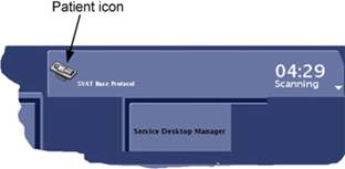
- In the Prescan Looping window, set Transmit Gain (TG) to 180.
Figure 18. Prescan Looping Window 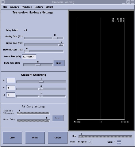
- Check the wattmeter to see if the reading is 16 kW ±
500 watts. If yes, proceed to the next step. If no, adjust the gain
for the body channel.
(For 16 kW XRFD amplifier) Rotate the single HD/BDY adjustment encoder on the RF amplifier front panel and, if necessary, increase the TG in small increments until the wattmeter reads 16 kW ± 500 watts when the TG is 200. Only adjust while the amplifier is actively pulsing. If output does not change, cycle amplifier power, wait 10 minutes, and then repeat the adjustment again.
Figure 19. Gain Adjustment Controls 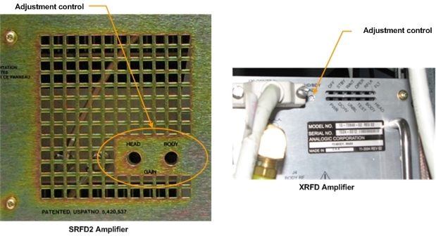
- From the scan desktop, click the CSD icon.
Figure 20. CSD icon 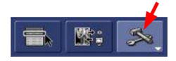
Calibrating UPM Forward Power for Body Channel
Procedure
UPM Functional Check for Body Mode
About this task
After completing the UPM calibration, continue with the UPM functional check.
Procedure
Disabling T/R, DD, and RF Input for Head Mode
Procedure
Using Bird Wattmeter and Power Adjustment Kit for RF Head Calibration
Setting up RF Coupler for Head Calibration
Procedure
- Insert the 5 kW element into the Forward sensor port, (green
4300A374-5). Make sure the arrow on the element points in the direction
of the arrow (from Input to Output) on the sensor. Lock the element
in place using the locking tab on the sensor.
Figure 21. RF Coupler Setup for Head Mode 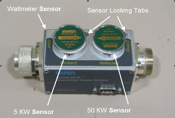
Wattmeter and Dummy Load Setup for Head Mode
Procedure
- Connect the input of the coupler to J3 on the front of the RF
amplifier:
Figure 22. Connection of RF Coupler to Head Output 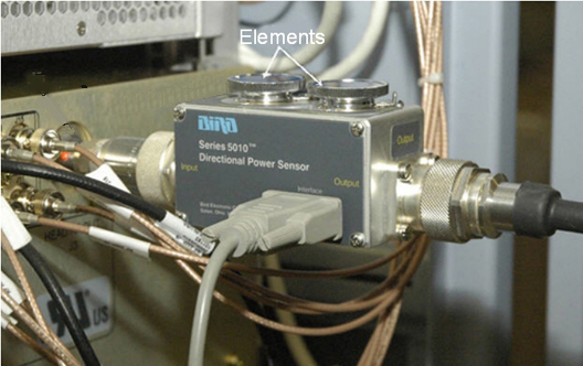
Connect the RF coupler output to the dummy load.Warning Figure 23. Complete Head Output Test Setup 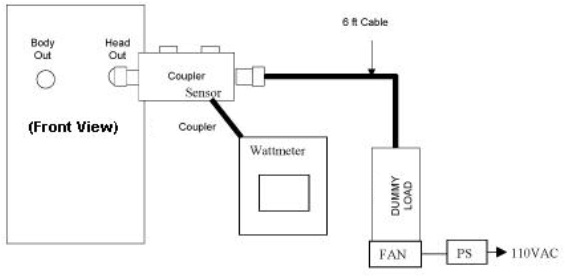
Setting up Bird 5000-EX Wattmeter to Measure Forward Head Maximum Power
About this task
This procedure is for the Bird 5000-EX. If you have a Bird 5000-XT, see Setting up Bird 5000-XT Wattmeter to Measure Forward Head Maximum Power.
Procedure
- Verify that the wattmeter display reads 43. If not, type 43 and then press Enter.
Figure 24. Wattmeter Display Set to Read Sensor Type - Some kits require an offset to ensure accurate measurement.
Locate the Element Offset Factors card in the kit.
Find the offset for “1.5T Head Output,” 2000 W.
Figure 25. Example Element Offset Factors Card - Press the Offset button on the wattmeter.
Enter the numeric value from the offset card, and press Enter.Note:
If entering a negative value, first enter the numerical value, then the minus symbol (–).
Figure 26. Wattmeter Set to Display Peak Power and Watts
Setting up Bird 5000-XT Wattmeter to Measure Forward Head Maximum Power
About this task
This procedure is for the Bird 5000-XT. If you have a Bird 5000-EX wattmeter, see Setting up Bird 5000-EX Wattmeter to Measure Forward Head Maximum Power.
Procedure
- Verify that the wattmeter display reads 43. If not, type 43 and then press OK.
Figure 27. Wattmeter Display Set to Read - Some kits require an offset to ensure accurate measurement.
Locate the Element Offset Factors card in the kit.
Find the offset for “1.5T Head Output,” 2000 W.
Figure 28. Example Element Offset Factors Card - Press ◄ to return to measurement mode.
Figure 29. Wattmeter Set to Display Peak Power and Watts
Using Agilent Wattmeter and Power Adjustment Kit for RF Head Calibration
About this task
Confirm that the Agilent wattmeter is still powered on. If the wattmeter has been turned off, it must be powered for at least 30 minutes for stable and accurate readings. The wattmeter must also be zero calibrated Agilent Wattmeter Setup.
Procedure
- Connect the remaining Agilent power components as shown below.
Figure 30. Agilent Wattmeter Setup for RF Power Output for Head 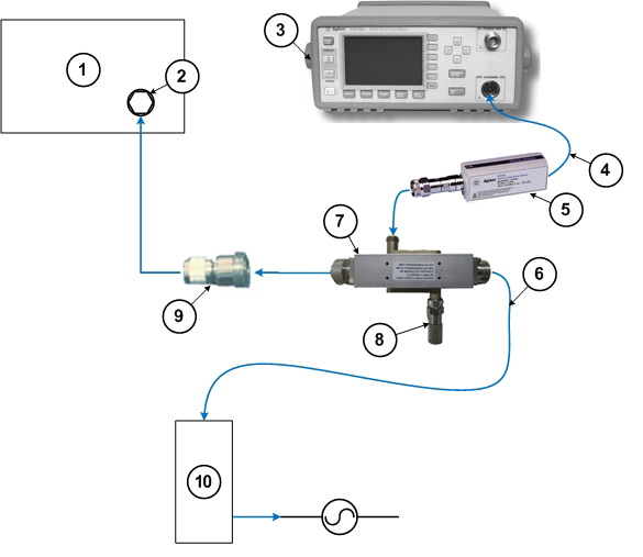
1 RF amplifier (front) 6 RF cable to dummy load 2 RF output port 7 RF coupler 3 Wattmeter 8 Agilent 50 ohm terminator connected to the Reflected port on the coupler 4 Agilent sensor probe cable 9 RF adapter 5 RF sensor connected to the Incident port on the coupler 10 Dummy load with internal fans
Adjusting RF Amplifier Output Power for Head Mode
Procedure
- Press Landmark. Then, advance to scan. A phantom is not needed. Note:
No phantom is needed since dummy command for head connection is set in UPM Tool Head mode for SIGNA Voyager.
Figure 31. Adv to scan 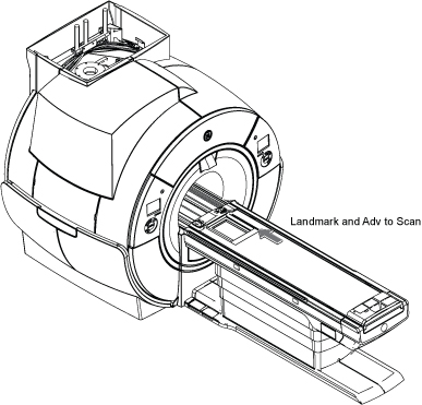
UPM Calibration for Head Mode
Procedure
UPM Functional Check for Head Mode
Procedure
- After completing the UPM calibration, continue with the UPM functional check.
- After the RF amplifier and UPM are calibrated for head mode, proceed to Finalization.
Finalization
Procedure
Warning
Set the RF ENB switch to DISABLE (down).Notice - Adjust connections as disconnect the RF coupler from J3 and reconnect the head transmit line.
- Re-enable the TR and DD fault switches on the front of the driver module. See Figure 1.
- Set RF ENB switch to ENABLE (up).
- Confirm that the other RF amplifier system cables are reconnected to their correct locations for clinical scanning.
- Perform Check Scan.
- If all the calibrations have been successfully made, perform a SaveInfo to save the UPM calibration results.