
- SIGNA™ Hero 3.0T Service Methods
- 5852800-8EN Revision 1.0
- 00000018WIA3076FE20GYZ
- id_131064183.0
- Aug 29, 2019 1:47:34 AM
Emergency Stop and Off Check
Prerequisites
| Required persons | Preliminary requirements | Procedure | Finalization |
|---|---|---|---|
| 1 | Not Applicable | Not Applicable | Not Applicable |
About this task
This document provides the procedure for checking:
-
The EMERGENCY STOP function of the Power Distribution Unit (PDU) for the Gradient subsystem, and RF subsystem.
-
The EMERGENCY OFF function of the power for the entire system.
The PDU EMERGENCY STOP buttons are located on the Operator Workspace Keyboard and on the Magnet Enclosure front cover (two buttons, left and right). An SYSTEM OFF button is located on the System Main Disconnect Panel. The other EMERGENCY OFF buttons are located by the customer.
ICN and Host PC Shutdown
Procedure
Emergency Stop
Procedure
- Press one of the EMERGENCY STOP buttons shown in the following illustration.
Figure 1. Emergency Stop Buttons 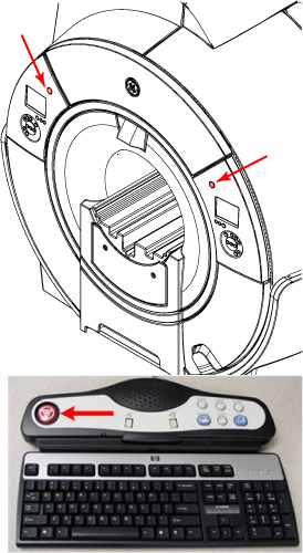
- Verify the power to the Gradient subsystem and RF subsystem is shut off.
- Gradient verification: Look at the SSSPS (Gradient Power Supply) Control Board and confirm the Enable LED is off (see Figure 2).
Figure 2. SSSPS LEDs 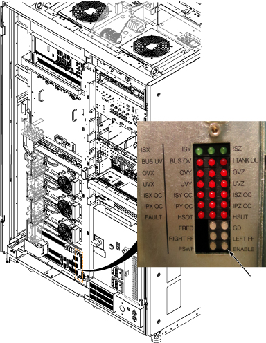
- RF Amplifier Verification: Look at the bank on the front of the RF Amp and confirm that the AC Power LED is off. (See Figure 3).
Figure 3. AC Power LED 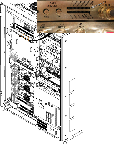 Note: Activation of the Emergency Stop Button for the ISC will remove the high voltage from the gradient power supply and the RF Amplifier. However, be aware that the PDU voltage will stay enabled in the ISC after the Emergency Stop Button is pressed.
- Gradient verification: Look at the SSSPS (Gradient Power Supply) Control Board and confirm the Enable LED is off (see Figure 2).
- On the PDU, press the EMO Reset Button to return power to all affected cabinets. See Figure 4 for ISC PDU.Note: When you press the EMO Reset button, you should hear the contactor engage. This is another indication that the E-Stop was pressed and is active.
Figure 4. Emo Reset and Input Test Points 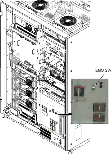
Emergency Off
About this task
The AC power for the Magnet Monitor is not controlled by the Emergency Off button.