If not already done, disconnect the ECG Cables from the ECG
port. (Figure 1 shows a pin diagram of the ECG connection.)
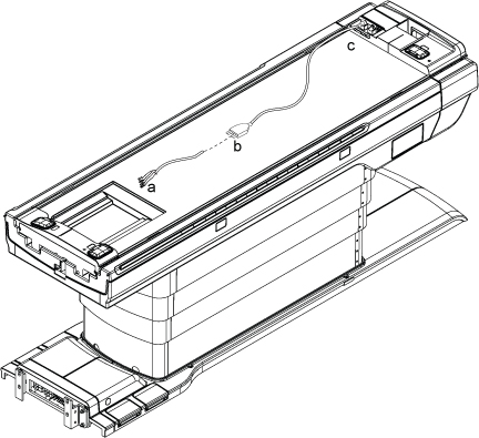
Figure 1. PIN Diagram of ECG Lead
Check the impedance of the ECG Cables from each of the leads
at point “a” to the other end of that lead at point “b.”
The impedance between point a and b should be 60k ohms ±5%
tolerance.
Check the impedance of the ECG Cables from each lead at point
“b” to its respective connection at point “c.”
The impedance should be 0 ohms.
Figure 2. Connections A and B on ECG Cables
Topic ID: id_SL2034326-1213232
Connect Leads and Plug ECG Leads to PAC
Procedure
Connect the white High Impedance MRI ECG Lead Wires to the grey
ECG Patient Cable by matching the colors on the white cable to the
colored dots on the grey cable.
Plug the open end of the grey ECG Patient Cable into the ECG
Port.
Topic ID: id_15364029
Finalization
Procedure
Return the system to the patient scanning condition.
Perform a check scan to ensure the system is operating properly.