- SIGNA™ Hero 3.0T Service Methods
- 5852800-8EN Revision 1.0
- 00000018WIA30A2FE20GYZ
- id_131066153.22
- Jan 26, 2022 2:01:03 AM
Cryocooler (F-50SH) setup
Prerequisites
| Personnel requirements | |||
|---|---|---|---|
| Required persons | Preliminary requirements | Procedure | Finalization |
| 2 | - | 120 minutes | - |
Shield/cryocooler installation
Procedure
- Open the Integrated Cooling Cabinet (ICC) cover and remove it.
Figure 1. Remove ICC cover 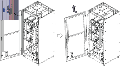
- Remove the bottom reinforcement bar by removing 6 screws.
Figure 2. Remove the bottom reinforcement bar 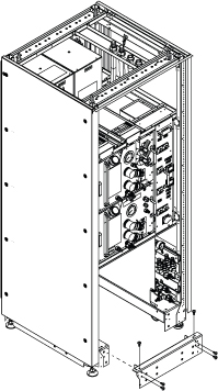
- Install the He line adaptors (long and short) and handle.
- Install the He line adaptor (long).
- Install the He line adaptor (short).
- Install the handle with 3 screws.
Figure 3. He line adaptors (long and short) and handle 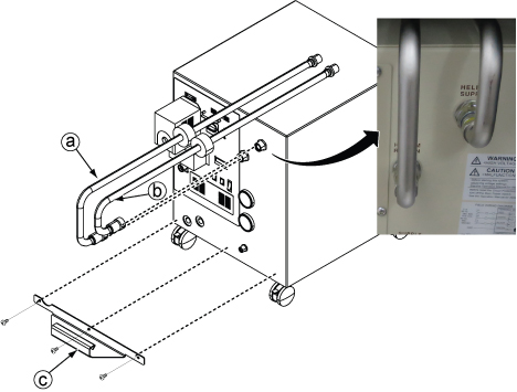
- Connect the E0011 and M0011 cables.
Figure 4. E0011 and M0011 connection 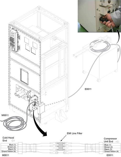
- Slide the F-50SH shield/cryocooler into the lower opening of ICC.
Figure 5. Shield/cryocooler installation 
- Do the following steps:
Figure 6. Copper mesh and elbow pipes 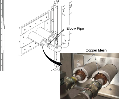
Equipment room hose and cable connection
Procedure
- Before routing the hoses and cables, make sure the hose/cable alignment on the tray is as shown below.
Figure 7. Equipment room cable tray cross-section view for standard (on the wall) siting 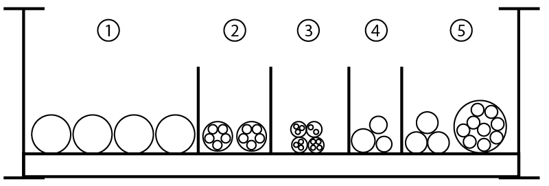
Section Description Contents 1 Water hose Red hose
Green hose
Facility water supply
Facility water return
2 Fiber optics E850
E5001
E5002
P5006
3 300V signal, 300V power, and 300V power/signal E3014
E3020
E3041
E3031
4 GND E4007
E4008
MDP-ISC
5 AC power cables E****
E0003
E0007
E0009
E0010
Note: E850 is the cable between F-50SH and MM4.Figure 8. Equipment room cable tray cross-section view for remote (off the wall) siting configuration 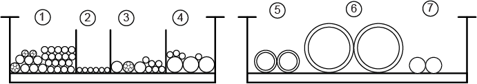
Item Description Contents 1 300V signal, 300V power, and 300 V power/signal M3314, M3311, M3313, M3315, M5001, M3023, M3022, M3391, M3379, M3300, M3339, 1265, 1502, M3030, M0011 2 Fiber optic P5001, P5006 3 >= 600V coax/RF and AC power M5003, M5004, M1305, M1350, and M1351 4 Gradient and RF and AC power M3317, M3318, M3319, M4005 5 Gas Lines (2) Run 621 cold head gas line Run 622 cold head gas line
6 Air Hoses (2) 4-inch air return (body coil)
4-inch air return (patent air)
7 Water Hoses (2) Blue water hose Black water hose
Note: * indicates optional cable
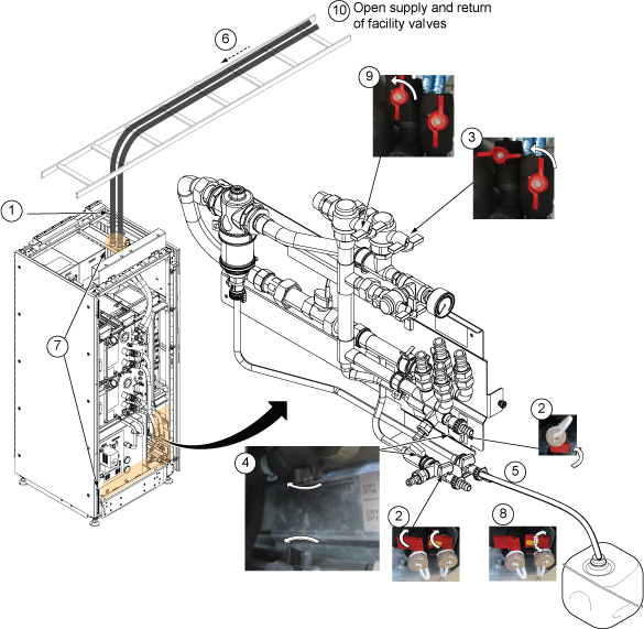
- Note: Make sure to route the hoses to avoid the hoist setup locations, which will be used for FRU replacement.Route the facility water hose on the tray and connect to the hose joint on the ICC.
Figure 9. Hose routing above ICC 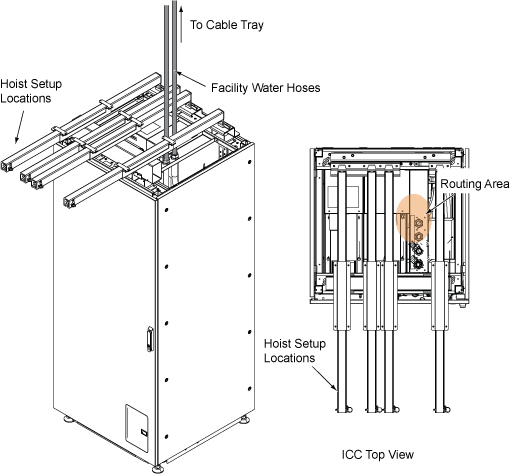
Figure 10. Facility water hose 
- Install the Water Flow Control Adapter (orifice) (5335002) according to the following steps:
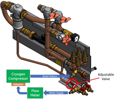 Note: The Water Flow Control Adapter (orifice) is shipped with the F-50SH.
- Wrap the male end of the orifice fitting with Teflon tape to prevent leaks.
- Insert the water flow adaptor and thread the male end into the coolant inlet port of the compressor. Tighten as appropriate to prevent leaks.
- Connect hoses according to Step step 4.
Figure 11. Water flow adaptor (orifice) installation 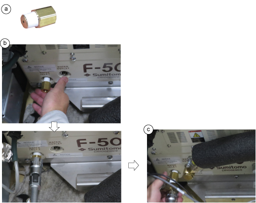
- Connect the hoses per the following steps:Note: Use the gray (5264039) and yellow (5264063) hoses only. DO NOT use the white hose supplied with flow (2333825).
- Note: Secure the hose band firmly to avoid a water leak.Cover the hoses with insulator.
Figure 12. 1/2-inch water hose connection 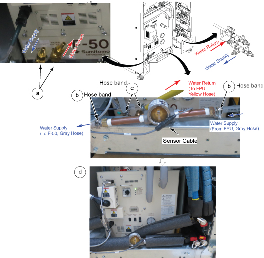
- Install the reinforcement bar with screws.
Figure 13. Reinforcement bar 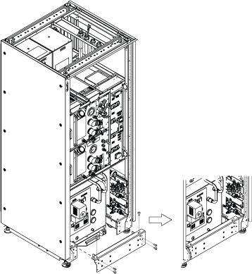 Note: (For Remote (off the wall) siting configuration) The cold head EMI filter should be de-installed from the ICC PW and installed on the Penetration Panel. Refer to Installing the coldhead EMI filter on the penetration panel.
 - Route and connect the F-50SH power cable (E0009) and sensor cable (Run 826).Note: F-50SH Power is provided by the MDP or facility PDU with a 30A breaker.
Figure 14. F-50SH power cable 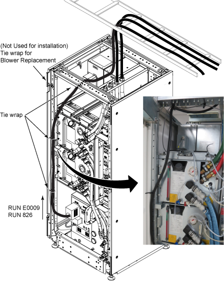
- (For Standard (on the wall) siting configuration) In the scan room, connect the cables for the magnet monitor and MRU.
(For Remote (off the wall) siting configuration) route the cables from the magnet monitor and MRU to the scan room through the penetration panel (without routing through the ICC).
Figure 15. Cables for magnet monitor and MRU 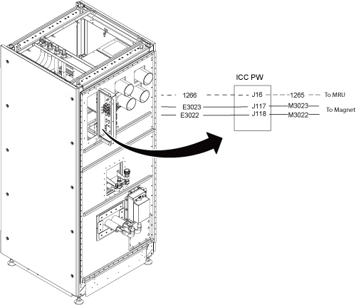 Note: For remote (off the wall) siting configuration, the BNC/DB filter is removed from the ICC PW and installed on the penetration panel. These cables do not pass through the ICC, they connect to the same location on the penetration panel.
Scan room hose and cable connection
Procedure
- Hose routing inside of the ICC PW cover will be as illustrated below.
Figure 16. Hose routing inside of ICC PW cover 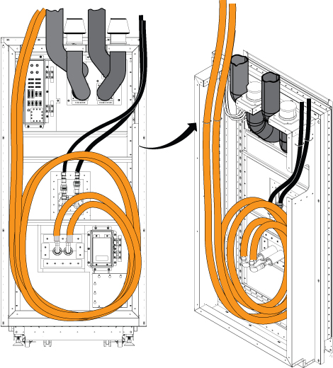
- Connect flexline and power line.
Figure 17. F-50SH and coldhead connection for standard (on the wall) siting configuration 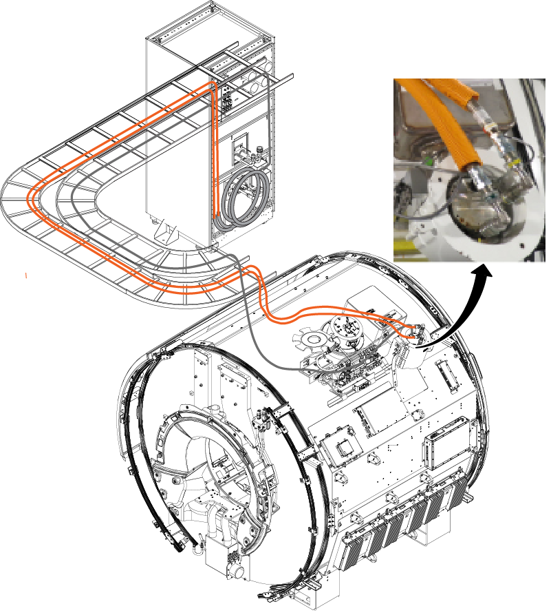
Figure 18. F-50SH and coldhead connection for remote (off the wall) siting configuration 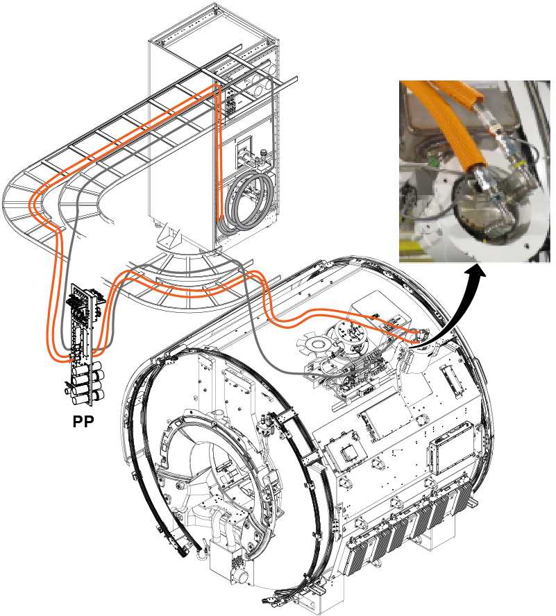
Figure 19. Scan room cable tray cross-section view for standard (on the wall) siting configuration 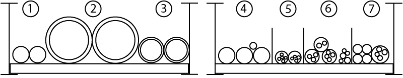
Item Description Contents 1 Water hoses Blue hose
Black hose
2 Air hoses 4-inch air supply - VRMw
4-inch air supply - patient air
3 Gas lines 621 cold head gas line
622 cold head gas line
4 Gradient cables and RF common GND M3317
M3318
M3319
M4005
5 Fiber optic P5001
P5006
6 300V signal, 300V power, and 300V pwr/signal cables 624
M3023
M3022
M3339
M3391
M5001
M5002
7 600V Coax/RF cables M5003
M5004
M1305
M1350
M1351
Figure 20. Scan room cable tray cross-section view for remote (off the wall) siting configuration Item Description Contents 1 300V signal, 300V power, and 300 V power/signal M3314, M3311, M3313, M3315, M5001, M3023, M3022, M3391, M3379, M3300, M3339, 1265, 1502, M3030, M0011 2 Fiber optic P5001, P5006 3 >= 600V coax/RF and AC power M5003, M5004, M1305, M1350, and M1351 4 Gradient and RF and AC power M3317, M3318, M3319, M4005 5 Gas Lines (2) Run 621 cold head gas line Run 622 cold head gas line
6 Air Hoses (2) 4-inch air return (body coil)
4-inch air return (patent air)
7 Water Hoses (2) Blue water hose Black water hose
Note: * indicates optional cable
Magnet Monitor cables and connection check
Procedure
- Make sure all cables are connected.
Figure 21. Hose and cables for standard (on the wall) siting configuration 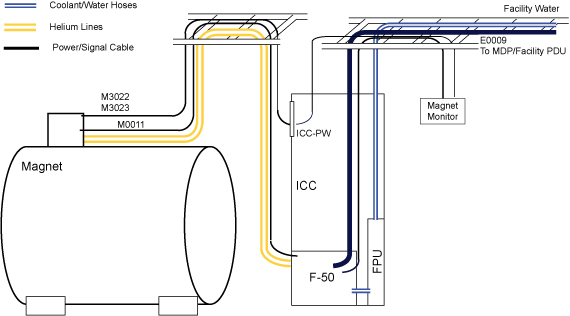
Figure 22. Hose and cables for remote (off the wall) siting configuration 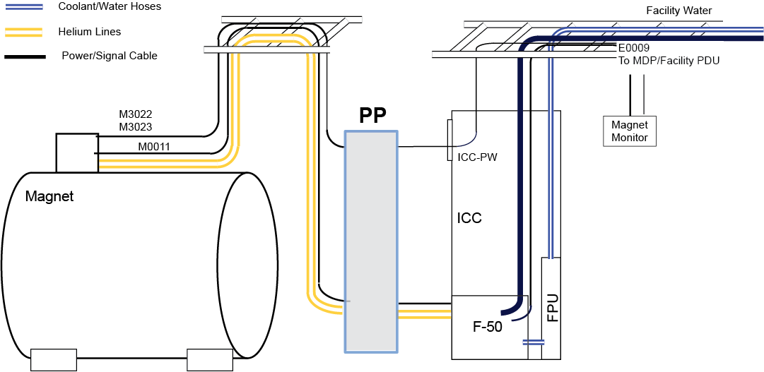
Figure 23. F50SH connection 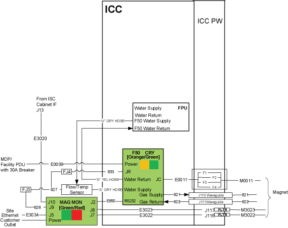 Note: For remote (off the wall) siting configuration, E3023, E3022 cables route through the penetration panel and do not route through the ICC.
Filling ICC primary water circuit
Procedure
- Note: Do not exceed the maximum pressure on the pressure gauge.Open valves of supply and return of the facility water as much as needed to read the gauge in between 50 L/min and 80 L/min (13.2 gpm and 21.1gpm).Note: Typical value of water flow is 60 L/min (15.8 gpm).
Figure 24. Valve operation