• SIGNA™ Hero 3.0T Service Methods
  • 5852800-8EN Revision 1.0
  • Object ID: 00000018WIA30050F20GYZ
  • Topic ID: id_13106349 Version: 5.0
  • Date: Nov 2, 2021 1:41:19 PM

PROBE/SV calibration and SNR tests

Prerequisites

Personnel requirements
Required personsPreliminary requirementsProcedureFinalization
1-90 minutes-
Tools and test equipment
ItemQuantityPart numberManufacturer
MRS phantom without the loader is required for the PROBE SNR and is used for the tuning process.12152220-
Form Support for ECMT and Phantom (included in system)-5554839-
Foam Support for Head Sphere (included in system)15554840-
Required conditions
The PROBE-S option (M3333WH) is required on-site to complete both the PROBE-S Cal & SNR Check and the PROBE-P Cal & SNR Check.
The PROBE-P option (M3333WG) is required on-site to complete both the PROBE-P Cal & SNR Check or the PROBE-P SNR Check only.

About this task

The catalogs being used are:
  • PROBE-P option
  • PROBE-S option which includes PROBE-P
  • Breast Spectroscopy
Topic ID: id_SL83015-1179773

Overview

About this task

This material describes two separate hydrogen only spectroscopy (PROBE/SV) procedures:
  • Echo peak location calibration (automated PROBE tuning script)
  • PROBE signal-to-noise ratio (SNR) performance test
Topic ID: id_SL1950995-1179773

PROBE/SV tuning and SNR procedure (echo peak location calibration)

Topic ID: id_SL3907455-1179773

Setup

Procedure

  1. If there is an exam running, end the current exam (unless the exam was started with the geservice patient ID).
  2. Check the MRS phantom temperature shown in green on the surface of the phantom and record it.
    Figure 1. MRS phantom temperature
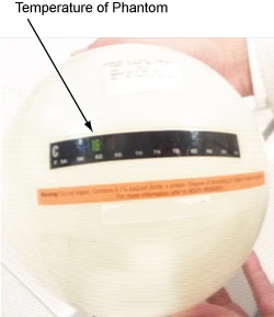
  3. Position the MRS phantom on the positioner. Phantom centering (up/down/left/right/in/out) within 25 mm of the isocenter in all directions is important. Landmark on the center of the phantom.
    Figure 2. Position the MRS phantom
Topic ID: id_SL1950996-1179773

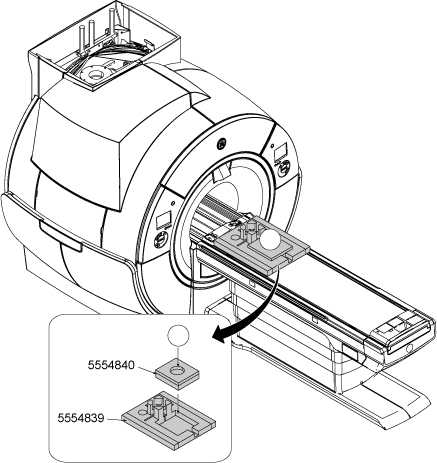
PROBE tuning and SNR check procedure

Procedure

  1. Start the PROBE tuning and SNR check tool:
    1. (For non-proprietary service tools) From the Common Service Desktop, select Calibration. Select PROBE Tuning and SNR Check from the Calibration menu, and select Click here to start this tool to start the procedure.
  2. PROBE tune UI appears.
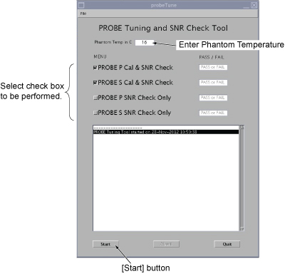
  3. Setup PROBE tune UI as follows.
    • Enter the phantom temperature recorded inSetup, Step 2.
    • Select the checkbox to be done.
    Note: If PROBE P Cal & SNR Check and PROBE S Cal & SNR Check are selected, it will take approximately 45 minutes to complete.
    Figure 3. PROBE tune UI
  4. Click Start. PROBE tuning/SNR scan will start after five minutes (after the phantom becomes stable).
    Figure 4. PROBE tune start screen
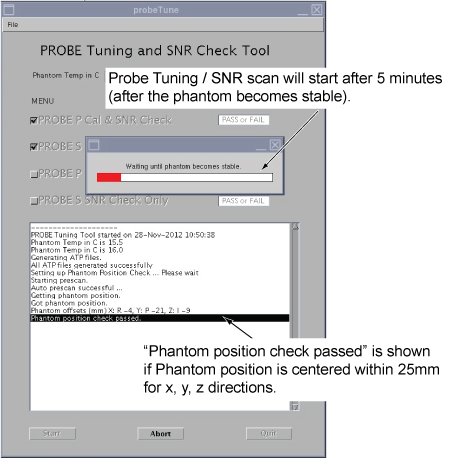
    Note: If the phantom is off-center by more than 25 mm, the following message will be displayed. In this case, set up the phantom, click OK in the message, and click Start again.

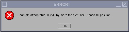
  5. The following screen will be shown once selected tests are completed and passed.
    Figure 5. PROBE tune complete screen

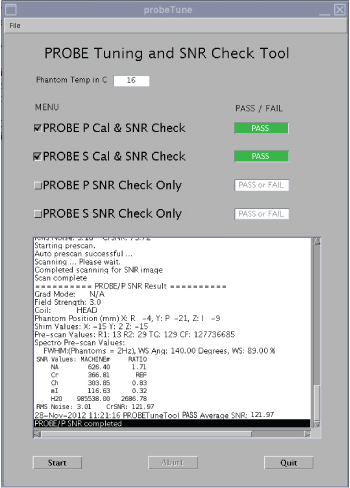
    If PROBE calibration fails, re-run grafidy, then try PROBE calibration again.

  6. To view the Calibration and SNR results, select Open from File pull-down menu.
    Figure 6. View result
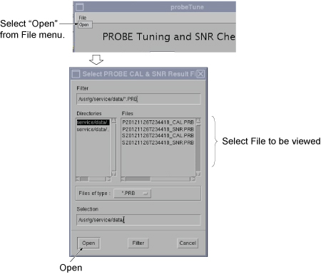
    Note: File Name example 1: P20121126T234418_SNR.PBR (PROBE P, Y=2012, M=11, D=26, Time=23:44:18, SNR)

    File Name example 2: S20121126T234418_CAL.PBR (PROBE S, Y=2012, M=11, D=26, Time=23:44:18, Cal)

    Figure 7. Example of File
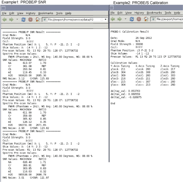
    Note: The specification criteria is as follows.

    PROBE-P/PROBE-S Calibration (absolute value)

    • Single delta parameter < 0.8
      Note: Single delta parameters are deltay_val, deltax_val, and deltaz_val.
    • Sum of all delta parameters < 1.0

    PROBE-P SNR (Average of 3 SNR scans)

    Cr SNR > 150

    PROBE-S SNR (Average of 3 SNR scans)

    Cr SNR > 90

  7. To view the complete results for troubleshooting purpose:
    1. Select C Shell.
    2. Type: more /usr/g/tools/ProbeTune/probe_cal_SNR.log and press Enter.
Topic ID: id_SL1951121-1179773

Troubleshooting

About this task

This section contains illustrations of PROBE SNR spectra, both incorrectly and correctly tuned, to show what a good spectrum looks like. During tuning or SNR troubleshooting, it may be necessary for a site to back up the original echoloc.dat file. This backup process requires renaming the file; otherwise, it will be overwritten during the tuning calibration. To get more information about the cause of an Auto-Water Suppression (AWS) failure, log the messages generated during the PROBE APS. A site may be required to send PROBE SNR raw data to an expert for review. This section also explains the P raw file location process and how to transfer it.
Topic ID: id_SL1951122-1179773

Example SNR spectra

About this task

Errors in the PROBE tuning calibration procedure can introduce changes in the appearance of the resulting PROBE SNR spectra. This section contains example spectra from a PROBE-P SNR protocol using the MRS phantom.

Procedure

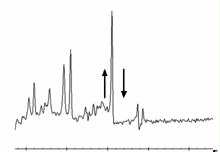
  1. Figure 8 shows a correctly tuned spectra. Pay particular attention to the base (left and right) of the NAA (NA) peak; this is the largest peak located at the center of the spectrum.
    Figure 8. Correctly tuned PROBE SNR spectra
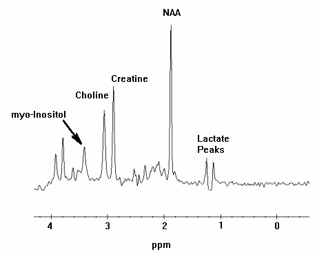
  2. Refer to Figure 9 and Figure 10 to view spectra with an uncalibrated tuning parameter (a delta was offset + or - from the correct value by 0.5 units).
    Figure 9. Incorrectly tuned PROBE SNR spectra
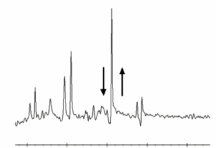
    Figure 10. Incorrectly tuned PROBE SNR spectra
  3. To perform PROBE tuning file and backup, follow these steps:
    1. At the MR Service Desktop, click C Shell.
    2. At the prompt, enter the following:

      su -

      Password: operator

      cd /usr/g/caldir Enter

      cp echoloc.dat echoloc.bak1 Enter

  4. Close the C shell.
    Note: The echoloc.dat file does not exist for initial software loads.

    The actual files that contain the PROBE calibration values are in the caldir directory as probesfix.dat and probepfix.dat. The unlabeled values are deltax, deltay, and deltaz.

    To get more information about the cause of an AWS failure, log the messages generated during the PROBE APS.

Topic ID: id_SL1951128-1179773

Directory creation

Procedure

  1. On the MR Service Desktop, click C Shell.
  2. Create a directory to hold the log file by entering the following:

    cd /usr/g Enter

    mkdir probe_data Enter

    cd probe_data Enter.

  3. Log in to the MGD AGP and direct the output to a file and to the screen. Use the pipe symbol (|) on the keyboard where indicated below. Local is the lowercase “l” key.
  4. rlogin agp | tee agp_log Enter.
  5. Log in using the user name agp , then press Enter. When prompted, enter the password agpservice and press Enter.

    At this point logging is running. DO NOT type anything in the AGP window. Watch the AGP messages appear on the screen; everything is logged to the file entered after the tee command (tee agp_log). This file is overwritten each time.

  6. Select the Rx Manager icon.
  7. Run Auto Prescan (APS).
    Note: No data appears in AGP_LX during APS.
  8. Select the Service Desktop Manager icon and use the scroll bar to review the log.
  9. When done, type logout in the AGP window. This disconnects the AGP from the C-shell. A message confirms the logout.
  10. To view the log file created, verify that the current directory is /usr/g/probe_data.
  11. Type more agp_log and press Enter.
  12. Close the C shell when you are done.
  13. The log file can be sent to the OLC, or e-mailed to whomever the site is working with to resolve any problems.
Topic ID: id_SL1951143-1179773

P raw data file location

About this task

During the troubleshooting process, the site may be required to identify the P raw data files generated when PROBE SNR was performed. These files may be helpful in determining a reason for an SNR failure. This portion of the procedure should be performed after running a PROBE SNR protocol to facilitate P raw file identification.

Procedure

  1. At the Service Desktop Manager, click C Shell.
  2. At the prompt, enter the following:

    cd /usr/g/mrraw Enter

    ls -lt P*| head Enter

  3. The most recent P files are displayed. The most recent P files are displayed on the top of this list. Record the PROBE raw data file (P####.7). The size of the P file is approximately 449584.
  4. Close the C shell when finished.
Topic ID: id_14989943

Finalization

Finalization

Remove all service equipment from the system.