
- SIGNA™ Hero 3.0T Service Methods
- 5852800-8EN Revision 1.0
- 00000018WIA30CCFE20GYZ
- id_131059253.3
- Jul 13, 2021 6:28:47 PM
Ground Leakage Current Test
Prerequisites
| Required persons | Preliminary requirements | Procedure | Finalization |
|---|---|---|---|
| 2 | Not Applicable minutes | 180 minutes | 5 minutes |
| Item | Quantity | Effectivity | Part number | Manufacturer |
|---|---|---|---|---|
| Dale 600 or 601 (120 VAC) or Dale 600E or 601E (220 VAC) Safety Analyzer | 1 | - |
600/601: 46-285647P1 or 46-328406G1; 600E/601E: 46-285647P14 or 46-328406G2 | - |
| Fluke ESA612 Electrical Safety Analyzer | 1 | - |
5453348-2 (220v) | - |
| Hazard Class 2 Personal Protective Equipment (PPE) | 2 | - |
| - |
| Digital Volt Meter (DVM) with Jumper Leads | 1 | - |
46-194427P284 | - |
| Personal Lock | 2 | - |
46-194427P320 | - |
| Red Warning LOTO Tag | 2 | - |
46-194427P322 | - |
| Multi-Locking Device (for multiple service technicians) | 1 | - |
46-194427P313 | - |
| ||||||||||||||||
| Condition | Reference | Effectivity |
|---|---|---|
|
All personnel performing this procedure must have completed proper electrical hazard training courses. | - | - |
|
Verify Ground Resistance Checks are completed and passed. | - | - |
|
Confirm all power and ground cables are installed correctly. | - | - |
|
Confirm the Main Disconnect of the PDU is ON. | - | - |
|
Confirm all subsystem cabinet circuit breakers and subsystem power switches are ON. | - | - |
|
Confirm Hazard Class 2 Personal Protective Equipment (PPE) is available. | - | - |
About this task
Before performing this procedure, personnel must have completed proper electrical hazard training courses, including
-
Power and Grounding Audit (GEHC-TECH-AMOL-CM9010) or equivalent
-
Electrical Safety Authorized Course (GE-EHS-280) or equivalent
This document contains a method for measuring Ground Leakage Current using different brands of Safety Analyzers. Only one of the Safety Analyzers listed in Tools and Test Equipment is required for this procedure.
Review and understand all Required Conditions before beginning this procedure.
| ||||
Ground Leakage Current Test
About this task
The following table highlights the tasks in the Ground Leakage Current Test procedure in the order that they should be performed. Some equipment listed are optional equipment and are only tested if on the system.
| Task to be performed | Go to section | Required/Optional |
| Record safety analyzer data and link to form | Recording Readings | Required |
| Set up the Safety Analyzer | Setting Up the Safety Analyzer | Required |
| Perform LOTO | Performing LOTO | Required |
| Measurement | Testing the System Ground Leakage Current | Required |
| Restore the System | Restoring the System | Required |
| Finalization Steps | End of document | Required |
Recording Readings
About this task
As this procedure is only performed when local regulations or codes require it, the readings gathered during this procedure must record for the local authority. A copy of the measurements should also be retained with the site documentation. Use the following tables to record your measurements. Mark any fields that are not applicable to the current location as “not applicable” or “N/A”.
| Safety Analyzer Information | ||
| Brand of Safety Analyzer | ||
| Safety Analyzer Model No. | ||
| Safety Analyzer Serial No. | ||
| Calibration Date | ||
| Date of Tests | ||
| Name of Tester (Printed) | ||
| Signature of Tester | ||
| Measuring Point | Max Leakage Current | if < 5.0 mA, PASS |
| Facility Disconnect | ||
Setting Up the Safety Analyzer
Procedure
- Two types of safety analyzers are available. Use the instructions for the safety analyzer that is available.
- Set up the safety analyzer near the front of the PDU.
-
Using the Dale Safety Analyzer:
- On the Dale Safety Analyzer, set the main selector switch to EXTERNAL.
Figure 1. Connections on Dale Safety Analyzer 
- On the Dale Safety Analyzer, set the main selector switch to EXTERNAL.
-
Using the Fluke ESA612 Safety Analyzer:
- Turn on the Fluke Safety Analyzer.
Figure 2. Fluke ESA612 Electrical Safety Analyzer 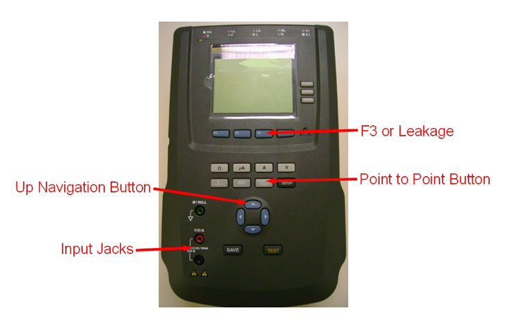
- Turn on the Fluke Safety Analyzer.
- The safety analyzer is now set up with the two leads attached and ready to be connected to the PDU.
Performing LOTO
Procedure
- Properly shutdown the system and Turn Off Main Breaker at ISC PDU.
- Turn Off MDP or Facility PDU breaker that supplies power to the system.
- Perform LOTO at the breaker of MDP or Facility PDU.
- At the secondarily terminal (output) of the main breaker, use a voltmeter to measure the voltage between each phase terminal and GND (ground). This reading should be <1V.
Testing the System Ground Leakage Current
Procedure
Setup Safety Analyzer per following steps.Warning - Disconnect the ground wire from the Facility Disconnect and attach it to the EXTERNAL clamp-type lead on the Safety Analyzer.
- Connect the Chassis clamp-type lead on the Safety Analyzer to the Facility Disconnect Ground Bus Bar.
Figure 3. Setup of Safety Analyzer 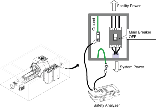
- Press the EMO RESET switch.
Figure 4. Main PDU Circuit Breaker 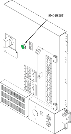
Restoring the System
Procedure
- Press the EMO RESET switch.
Figure 5. Main PDU Circuit Breaker
Finalization
Finalization
If this procedure is being performed at a time other than initial installation, run Check Scan (Good-Bye) to ensure the system is ready for patient scanning.
If this procedure is being performed as part of installation, proceed with installation instructions.