
- Discovery MR750 3.0T System Service Methods
- 5690009-2EN Revision 4
- 00000018WIA302AAE20GYZ
- id_131059283.16
- Nov 29, 2021 11:01:35 AM
RF body coil replacement
Prerequisites
| Required persons | Preliminary requirements | Procedure | Finalization |
|---|---|---|---|
| 2 minimum | Not Applicable | 240 minutes | 40 minutes |
| Item | Quantity | Effectivity | Part number | Manufacturer |
|---|---|---|---|---|
| Small Carpenter’s Level | 1 | - | - | - |
| Field RF Coil Tuning Kit | 1 | - |
5311727 | - |
| Nonmagnetic Titanium Service Tool Kit, Large Set | 1 | - | 5112581 | - |
| Arc Detection Stress Test Kit | 1 | - |
5401455-2 | - |
| Elliptical Phantom and Test Fixture (for 750 Dual Drive Only) | 1 | - |
5313739 | - |
| Item | Quantity | Effectivity | Part number | Manufacturer |
|---|---|---|---|---|
| Adhesive | 1 | - |
46-220312P1 | - |
| Anti-Seize | 1 | - |
2119594 | - |
| Item | Quantity | Effectivity | Part number | Manufacturer |
|---|---|---|---|---|
| Discovery MR750 3.0T Body Coil and FRU Case | 1 | - |
See FRU Manual. | - |
| FRU Kit for End Bell Foam Replacement 450, 750, 450w, 450w GEM (for 750 Dual Drive Only) | 1 | - |
5498152 | - |
| ||||||||
| Condition | Reference | Effectivity |
|---|---|---|
| Contact a trained, local body coil tuning expert before starting this procedure, because the coil will need to be tuned as part of the replacement finalization. If necessary, contact the Modality Operations Manager for a list of trained individuals. | - | - |
About this task
Use this procedure to replace the RF body coil.
Remove RF body coil
Procedure
- Disconnect the bore lights from the RF body coil. Pop out the four pop pins before removing the bore lights.
Figure 1. Bore lights 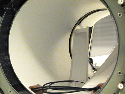
- Notice: Do not use the air hose manifolds to remove the RF body coil.Partially slide out the old RF body coil, and disconnect the bore temperature sensor and tape it to the magnet enclosure so it is out of the way.
Figure 2. Bore temperature sensor cable 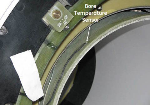
- Notice: Do not use the air hose manifolds to remove the RF body coil.Fully remove the coil and set it aside on the patient end.
Figure 3. Removing RF body coil 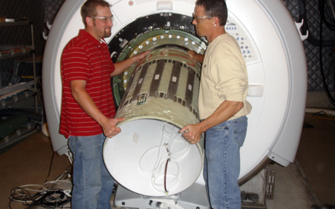
Figure 4. RF Body Coil on Patient End 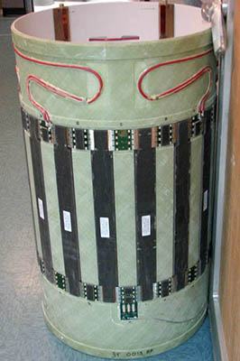
Install RF Body Coil for Single Drive
Procedure
- Slide the new body coil into the magnet bore. The DD bias lines are in the front and the I and Q connectors face the rear.
Figure 5. Sliding in RF Body Coil 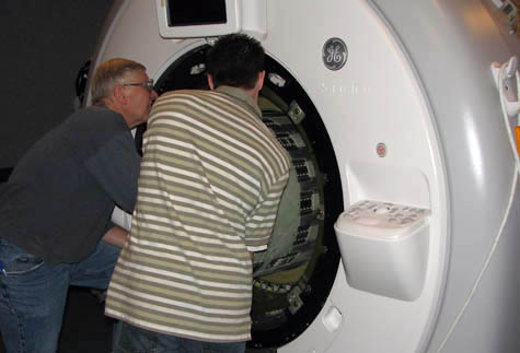
- Align the I and Q connectors in the rear so they are as close to the 7 o’clock and 5 o’clock positions as visually possible.
Figure 6. Centering RF Body Coil 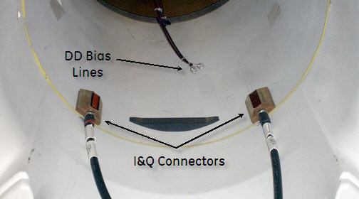
- Reconnect the DD bias lines and I and Q lines.
Figure 7. Reconnecting DD bias lines 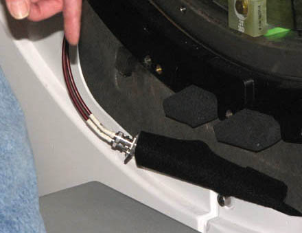
Figure 8. I and Q connectors 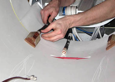
Body Coil Alignment
End Bell to Body Coil Gap Check
Procedure
- The gap tool (5391159) has three sections to help measure the gap.
Figure 9. Gap check using gap tool 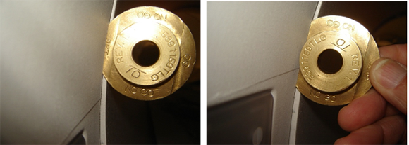
- The NO GO section is 3.0 mm. If the NO GO section can fit in the gap, then the gap is too wide.
Figure 10. Example: improper gap between front/rear end bell and RF body coil (too large) 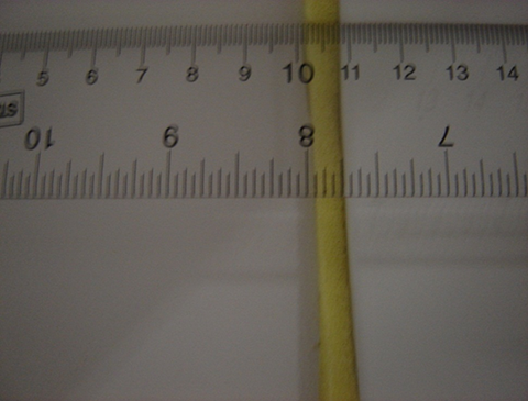
- The GO portion is 2.0 mm. If the GO section cannot fit in the gap, then the gap is too narrow.
Figure 11. Example: improper gap between front/rear end bell and RF body coil (too small) 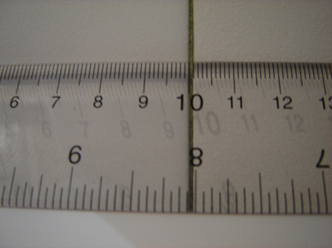
-
The SET section is 2.5 mm. This is the widest the gap can be. Ideally the gap should be 2.0 mm; therefore, the gap should actually be positioned with the GO section of the tool when adjusting end bells.
Figure 12. Example: proper gap between front/rear end bell and RF body coil 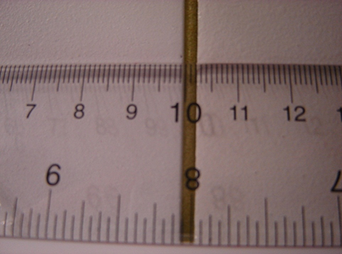
The proper gap is important and required to help keep the parameters of the system (such as uniformity, projection, body coil tuning) in specification. Measure the gap on the front AND rear end bell, and also in multiple locations around the circumference, including under the bridge.
Confirm the gaps between the front and rear end bells are between 2 mm and 2.5 mm around the entire circumference.
If the gaps on the front and rear end bells are correct, proceed to Manual pre-scan projection — image test.
If the gaps are not between 2 mm and 2.5 mm, proceed to Front end bell gap adjustment.
- The NO GO section is 3.0 mm. If the NO GO section can fit in the gap, then the gap is too wide.
Front end bell gap adjustment
Procedure
- Note: There is no way to directly adjust the front end bell. However, if adjustments are needed, align the body coil with the front end bell by moving the body coil. When the gap between the front end bell and the body coil is 2.0 mm to 1.5 mm, make the proper adjustments to the rear end bell.Move the front end bell in place on the system. Start all M10 x 25 screws and nylon washers in place. Starting at the top (12 o’clock position), begin tightening screws.
Figure 13. Tightening screws on front end bell 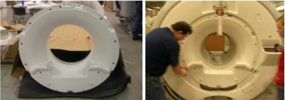
- Work around the end bell, tightening all screws about 2 turns per rotation. Move the RF coil forward or backward so that the minimum gap achieved (anywhere around the circumference of the RF coil and end bell interface) is 2 mm.
Figure 14. Gap check using gap tool
Rear end bell adjustment
Procedure
- Move the rear end bell (out or in) to get a gap of 2 mm to 2.5 mm (desired gap is 2 mm) between the RF coil and rear end bell. Also account for the 2 mm to 2.5 mm gap required for the front end bell.
The rear end bell has adjustable studs (circled in image below) to which the end bell mounts. Adjust the studs by loosening the nuts on the shorter standoffs on the rear turtle ring arms (where the rear end bell will be mounted).
Figure 15. Adjusting gap between read end bell and RF body coil 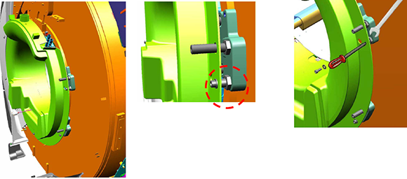
Manual pre-scan projection — image test
Procedure
- Note: To perform this procedure, the service key must be installed.Note: The Manual Prescan Projection test must be done with the end bells securely attached to the magnet in order to obtain the proper results.Place the split bridge temporarily (without attaching the drive belt or mounting hardware) into the magnet. Engage the four M10 threaded bolts with the rear pedestal and set the L-brackets that are still attached to the upper bridge support bracket onto the lower bridge support bracket.
Figure 16. Upper bridge support bracket on lower bridge support bracket 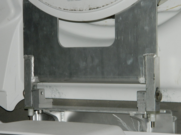
- When the single scan completes, two pop-ups appear. One is titled “Profile of ePhantom”; the other is titled “Uniformity Plot of ePhantom.”
Figure 17. Profile of ePhantom 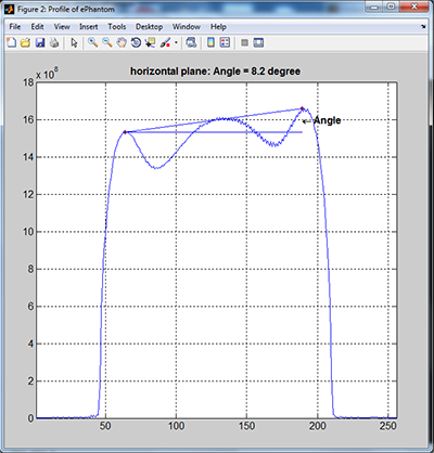
Figure 18. Uniformity plot of ePhantom 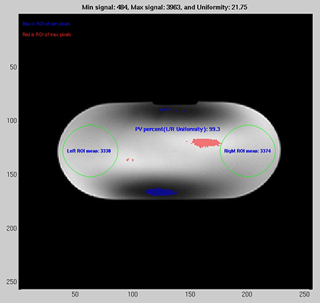
RF body coil alignment — centering pads
About this task
| Centering Pad PN | Mark on Centering Pad | Thickness with Double Sided Tape Applied (mm) |
| 5498416 (default) | None | 5.46 |
| 5498416-2 | 2 | 5.71 |
| 5498416-3 | 3 | 5.97 |
| 5498416-4 | 4 | 6.22 |
| 5498416-5 | 5 | 6.48 |
| 5498416-6 | 6 | 6.73 |
| 5498416-7 | 7 | 6.98 |
| 5498416-8 | 8 | 7.24 |
| 5498416-9 | 9 | 7.49 |
Procedure
- Place a small piece of tape on the gradient coil acoustic liner so that the body coil position is clearly marked. This tape is used to align the body coil for the remainder of the procedure each time the body coil is re-installed.Note:
The body coil levelness (with respect to the x-axis) is very important for the projection angle. From this point on, align the body coil using the side of the coil (right or left) that does NOT need a thicker centering pad. The tubular level (5450084) is no longer used because it was required for the baseline body coil alignment in Body Coil Alignment.
Figure 19. Temporary body coil alignment — tape on left side 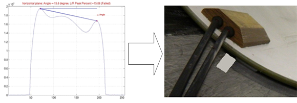 Note: If the scan projection obtained looks similar to the illustration below, add a small piece of tape to the FRONT RIGHT (when looking at the magnet from the front) centering pad corner. Based on the direction that the projection angle is shown (which correlates with a positive sign on the angle), the thicker centering pads need to be installed on the LEFT side of the coil when looking at the magnet from the front.
Figure 20. Temporary body coil alignment tape on right side 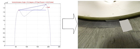
- Fully remove the RF body coil and set it on the patient end. Install new centering pads (using the double sided tape and screw) using the following table as a guideline for determining which of the thicker centering pads should be used.
- If the Uniformity result has positive sign, the thicker centering pads should be installed on the LEFT side of the coil when looking at the magnet from the front.
- If the Uniformity result has a negative sign, the thicker centering pads should be installed on the RIGHT side of the coil when looking at the magnet from the front.
Table 8. Number of centering pads by projection angle Projection Angle (degrees) Centering Pad (FRONT) Centering Pad (REAR) 0–3 baseline baseline 3–6 2 baseline 6–9 2 2 9–12 3 2 12–15 3 3 15–18 4 3 18–21 4 4 21–24 5 4 24–27 5 5 27–30 6 5 30–33 6 5 33–36 7 6 36–39 7 7 39–42 8 7 42–45 8 8 45–48 9 8 48–51 9 9 Note: Either the left or right side of the coil should retain the standard, or baseline, centering pads (5498416). Add thicker centering pads to only one side of the body coil.Figure 21. Projection Angle Example 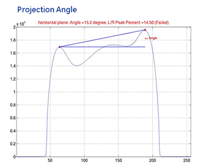
The example Projection Angle result is 15.2 degrees, so the suggested centering pads to use are a ‘4’ in the FRONT and a ‘3’ in the REAR as shown in the table below. Based on the direction that the projection angle is tilted and because it has a positive sign, both the centering pads should be added to the LEFT side of the coil when looking at the magnet from the front.
Figure 22. Centering pads used for projection angle 15.2° 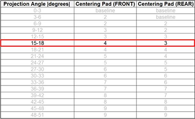
- Install new centering pads based on the following guidelines:
- If the FRONT centering pad is equal to or thicker than the REAR centering pad, use Table 9.
Table 9. Extra pad quantities by projection angle (equal to or thicker scenario) Projection Angle (degrees) Centering Pad (FRONT) Centering Pad (REAR) 3–6 No Change Previous Pad + 1 6–9 Previous Pad + 1 Previous Pad + 1 9–12 Previous Pad + 1 Previous Pad + 2 12–15 Previous Pad + 2 Previous Pad + 2 15–18 Previous Pad + 2 Previous Pad + 3 18–21 Previous Pad + 3 Previous Pad + 3 21–24 Previous Pad + 3 Previous Pad + 4 24–27 Previous Pad + 4 Previous Pad + 4 Note: The final centering pads used should be within 1 thickness step of one another to optimize the balance between the front and rear. For example, if a ‘4’ centering pad was used in the FRONT, then the REAR must use a ‘3’, ‘4’, or ‘5’ centering pad.Equal to or Thicker Scenario:
If the previous centering pads installed were a ‘4’ in the FRONT and a ‘3’ in the REAR, and the Uniformity resulted in an angle between 9 and 12 degrees, then the centering pads should be changed to a ‘5’ in the FRONT and a ‘5’ in the REAR.
Figure 23. Extra pad placement for equal to or thicker scenario 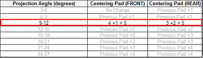
- If the FRONT centering pad is thinner than the REAR centering pad, use Table 10.
Table 10. Extra pad quantities by projection angle (thinner scenario) Projection Angle (degrees) Centering Pad (FRONT) Centering Pad (REAR) 3–6 Previous Pad + 1 No Change 6–9 Previous Pad + 1 Previous Pad + 1 9–12 Previous Pad + 2 Previous Pad + 1 12–15 Previous Pad + 2 Previous Pad + 2 15–18 Previous Pad + 3 Previous Pad + 2 18–21 Previous Pad + 3 Previous Pad + 3 21–24 Previous Pad + 4 Previous Pad + 3 24–27 Previous Pad + 4 Previous Pad + 4 Note:The final centering pads used should be within 1 thickness step of one another to optimize the balance between the front and rear. For example, if a ‘4’ centering pad was used in the FRONT, then the REAR must use a ‘3’, ‘4’, or ‘5’ centering pad.
Thinner Scenario
If the previous centering pads installed were a ‘2’ in the FRONT and a ‘3’ in the REAR, and the Uniformity resulted in an angle between 9 and 12 degrees, then the centering pads should be changed to a ‘4’ in the FRONT and a ‘4’ in the REAR.
Figure 24. Extra Pad Placement for Thinner Scenario 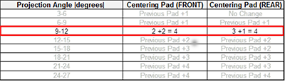 Note:
Note:If the new centering pads were too thick and your projection angle is now outside of the target +/- 3 degree range in the opposite direction (meaning the sign of the angle has flipped from positive to negative or negative to positive and the tilt of the projection scan is going in the opposite direction), reduce the thickness of the centering pads assuming a single pad step is equivalent to 3 degrees.
For example, suppose the previous Uniformity result was +10. Per the table above, a ‘3’ centering pad would have been used in the FRONT, and a ‘2’ centering pad would have been used in the REAR. If the new Uniformity result is ‘-5’, then the centering pads used were too thick. Reducing one of the pads should make the Uniformity result go from ‘-5’ to ‘-2’ and reach the desired +/- 3 degree range. Because the goal is to optimize the balance between the front and rear, the ’3’ centering pad used in the FRONT should be changed to a ’2’.
- If the FRONT centering pad is equal to or thicker than the REAR centering pad, use Table 9.
Finalization
Procedure
- Note: RF coil tuning can be done only by personnel who have successfully completed GE Healthcare’s training class for Body Coil Tuning and Stress Test, GEHC-TECH-AMSC-MR5037.Have the previously contacted, properly trained body coil tuning expert tune the RF body coil.
- Run TR Dynamic Disable Calibration.
- Run Troubleshooting the Daily Quality Assurance (DQA) II tool.
- Run LVShim — Gradshim.
- Run System gain calibration.
- Run Echo Planar Test (EPT).
- Do SaveInfo.
- Do a quick head and body scan to ensure the system is functioning properly.