
- SIGNA MR355 / SIGNA MR360
- Service Manual
- 5856356-3EN Revision 5.0
- Basic Service Documentation. Copyright General Electric Company.
- 00000018WIA30F68F20GYZ
- id_131063963.0
- Feb 21, 2021 9:11:31 PM
System Gain Calibration
Prerequisites
| Required persons | Preliminary requirements | Procedure | Finalization |
|---|---|---|---|
| 1 | Not Applicable | Head and Body = 20 mins; Body = 10 mins; Head = 10 mins minutes | Head and Body = 2 mins; Body = 2 mins; Head = 2 mins minutes |
| Item | Quantity | Effectivity | Part number | Manufacturer |
|---|---|---|---|---|
| Head Sphere with Loader for 1.5T | 1 | - |
2125244 | - |
| Head Loader Positioner | 1 | - |
5110241 | - |
| Body Sphere | 1 | - |
46-265635G6 | - |
| Body Loader | 1 | - |
2135652-2 | - |
| ||||
| Condition | Reference | Effectivity |
|---|---|---|
|
No required conditions. | - | - |
About this task
System gain calibration is performed to determine the standard head (transmit/receive coil) and body recon scale factors that will achieve a known level of image intensity when using the standard head coil or body coil with a known phantom solution and protocol. The goal is that when the same solution or tissue is scanned in either the standard head or body coil with the same protocol, those tissues will have approximately the same image intensity level on a given system and between systems of like type.
This calibration accounts for differences in standard head and body receive coil sensitivity, preamp gains, cable loss, receiver gain, and other factors. The calibration must be done on standard head and body at least once to calibrate those paths. The procedure can calibrate both standard head and body together, only head, or only body. System gain calibration consists of:
-
Head and Body Calibration.
Note:Although these calibrations can not be run simultaneously, they can both be selected at the same time to run serially. Otherwise, run individual modes as listed in the next two options.
-
Body Calibration.
-
Head Calibration.
Preliminary Setup
Procedure
- Position the head sphere in the head loader and fasten the strap.
Position the head loader on top of the head loader positioner in the
head coil so the loader's black center line lies directly below the
head coil's superior/inferior center marker.
Figure 1. Position Head Sphere in Head Loader 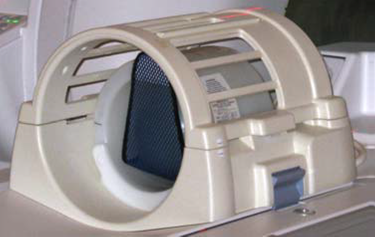
Figure 2. Landmark head sphere 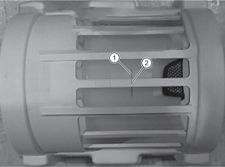
1 Black line on loader 2 S/I center line on coil - Note:Landmark on the head coil. As the calibration runs, the table will move to the body coil scan by itself.
The distance between head loader landmark and center-mark on body loader.
Figure 3. Phantoms Lined Up 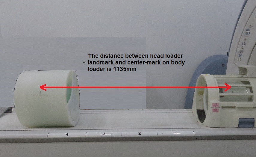
- Start the System Gain Calibration Tool.
-
Starting restricted service tools available to GE Field Service:
-
Ensure that a service key is installed.
-
Select Calibration Wizard from the calibration menu and select Click here to start this tool to launch the wizard.
-
Select System Gain Calibration from the menu and review and verify the prerequisites are met.
-
Select Click here to start this tool to start the procedure.
Figure 4. Starting Sys Gain Cal from ICW 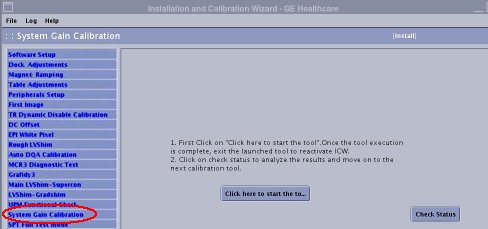
If you are unable to start the Restricted Service tools, use the non-proprietary method described in the next bullet.
-
-
Starting non-proprietary service tools:
-
From the Common Service Desktop, select Calibration.
-
Select System Gain Calibration from the calibration menu, and select Click here to start this tool to start the procedure.
Figure 5. Starting System Gain 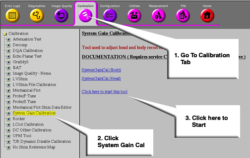
-
-
- Phantom Setup (sites without a nesting plate)
-
With landmark still set on the Head Loader,drive the table in until the position reads 1135mm.
Figure 6. Distance Between Head Coil Landmark and Centerline on Body Loader -
Without moving the table, move the Body SNR Sphere with body loader so the laser is on the black centerline of the loader.
-
Place the foam pads/wedges on both sides of the Body Loader to prevent roll.
-
Advance to Scan.
-
Head and Body Calibration
Procedure
- In the System Gain Tool window, select Head & Body and then select START. Calibration begins.
Head gain is calibrated first. When head is complete, body is calibrated. The illustrations below apply to both head and body.
Figure 7. Starting Head and Body Calibration 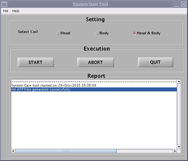
- The calibration results show on the screen. If adjustments are
required, the system asks, Do you want to save the recon
scale factor? Click Yes to save
the recon scale factor.Note:
There are (at least) two prompts: one for head and one for body.
Figure 8. Calibration Output 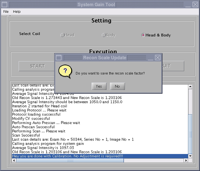
Body Calibration
Procedure
- Note:Select Body, and then click START. Calibration begins. (See Figure 7.)
The system is dependent on landmarking the head coil, even for body mode only scans.
- When the test is complete, the calibration results show on the screen. If adjustments are required, the system asks, Do you want to save the BODY recon scale factor? Click Yes to save the calibration file. (See Figure 8.)
- Click QUIT to exit the tool. The calibration is complete.
Head Calibration
Procedure
- Select Head, and then click START. Calibration begins. (See Figure 7.)
- When the test is complete, the calibration results show on the screen. If adjustments are required, the system asks, Do you want to save the HEAD recon scale factor? Click Yes to save the calibration file. (See Figure 8.)
- Click QUIT to exit the tool. The calibration is complete.
Finalization
Procedure
- Remove all phantoms and service tools from the patient table.
- If you are performing this calibration during an installation, continue with the required calibrations. Otherwise, perform a SaveInfo to save the new ReconScale values.