- id_12374007
- Version: 1.5
- Date: Jul 5, 2019 10:03:32 PM
eXtreme Gradient Power Supply Replacement
Prerequisites
| Required persons | Preliminary requirements | Procedure | Finalization |
|---|---|---|---|
| 1 | 5 minutes | 90 minutes | 5 minutes |
| Item | Quantity | Effectivity | Part number | Manufacturer |
|---|---|---|---|---|
| Hoist Service Kit | 1 | - |
5196226 |
- |
| Non-magnetic Tool Kit (or equivalent) | 1 | - |
5113258 |
- |
| Item | Quantity | Effectivity | Part number | Manufacturer |
|---|---|---|---|---|
| Towels | N/A | - | - | - |
| Nitrile Gloves | As needed | - | - | - |
| Item | Quantity | Effectivity | Part number | Manufacturer |
|---|---|---|---|---|
| XPS Unit | 1 | systems with XPS units |
See FRU manual. |
- |
| XP2 Unit | 1 | systems with XP2 units |
See FRU manual. |
- |
note:
|
| Condition | Reference | Effectivity |
|---|---|---|
|
Perform LOTO on the PGR cabinet before replacing an XPS unit. See the MR Service Safety Manual, PN 5452735. |
- | - |
|
Before disconnecting any cables on the front of an XPS unit, shut down the PPMP at the HEC. Press ▲ and F3 simultaneously to stop the pump. Next, switch the PPMP circuit breaker to OFF. |
- | - |
Overview
This procedure describes how to replace an eXtreme Gradient Power Supply (XPS or XP2) unit in the PGR cabinet. The power supply unit weighs about 160 pounds, so the use of a hoist kit is required. This procedure details the correct way to use a hoist kit to safely remove the power supply unit and replace it with a FRU.
The system contains either XPS or XP2 units. These units have the same form factors, but are not interchangeable. A system will have either all XPS or all XP2 units. Make sure you order the correct FRU for the system.
This procedure refers to both units as XPS.
Procedure
- Perform LOTO on the PGR cabinet. See the MR Service Safety Manual, PN 5452735.
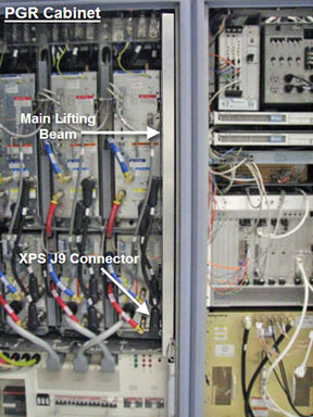
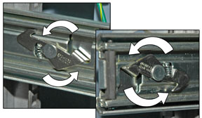
- Before setting up the hoist kit, detach the XPS J9 connector
to properly remove the main lifting beam.
Figure 1. Lifting Beam and J9 Connector in PGR Cabinet
- See Hoist Service Kit and Lifting Accessories to set up and secure the hoist.
- notice
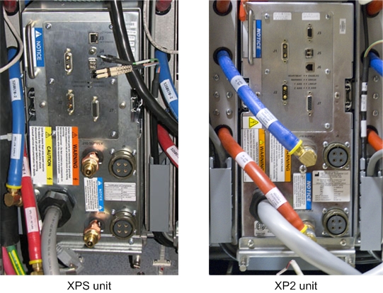
- Disconnect the cables and hoses from the front of the XPS unit.
This includes the XPS to XGA power cables, coolant lines, and fiber-optic
cables.
Figure 2. Front of XPS and XP2 Units - Cables Disconnected
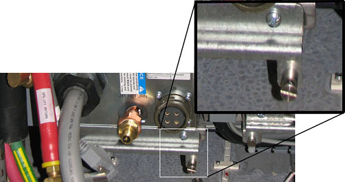
- Unscrew the four screws from the bottom of the module retaining
bracket of the XPS unit. (The bottom two screws are captive screws,
and will not fully detach from the bracket.) Completely remove the
module retaining bracket and set it aside. It is required for the
FRU.
Figure 3. Module Retaining Bracket
 note:
note:If replacing the X-axis XPS, you may remove the PGR cabinet door and lean it against the side of the cabinet. Tape the free end of the green/yellow ground wire detached from the upper part of left door to the PGR cabinet frame so the ground does not contact the L1, L2, or L3 AC mains power connections in the terminal strip in the upper left part of the PGR cabinet.
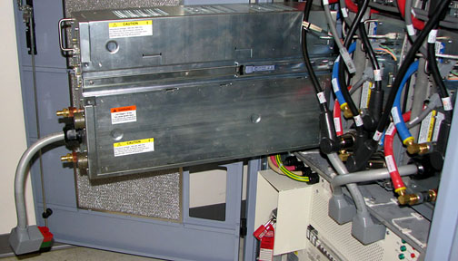
- Carefully slide out the XPS unit until the top is completely
exposed, but the unit is not fully out of the PGR cabinet.
Figure 4. Sliding Out XPS Unit
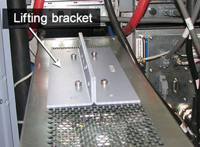
- Place the lifting bracket from the FRU crate on top of the XPS
unit. Attachment screws are stored on the bracket. Match the four
openings and screw in the lifting bracket.note:
The back two screw holes are slightly offset. Ensure the lifting bracket is placed correctly on top of the XPS unit so the screws are completely intact.
Figure 5. Lifting Bracket Inside FRU Crate
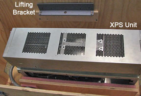
Figure 6. Lifting Bracket Attached to XPS Unit
 warning
- Hook the winch from the hoist kit to the lifting bracket, and ratchet the winch to tighten the chain.
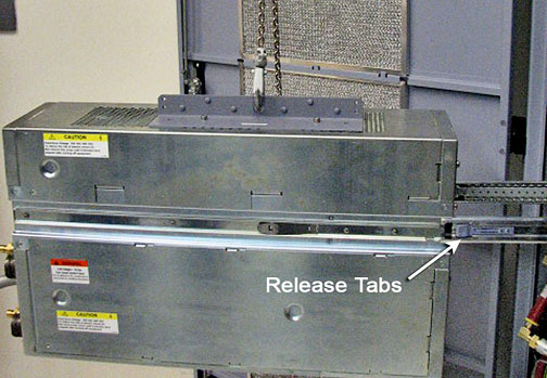
- With the XPS unit held by the slide rails and the hoist kit,
extend the unit until the slide rails lock. Press the release tabs
in on each side while pulling the unit out of the PGR cabinet.note:
When the XPS unit is leveled with the hoist, the rails will move freely. If they do not, adjust the hoist.
Figure 7. XPS Unit - Extended Out of Cabinet
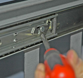
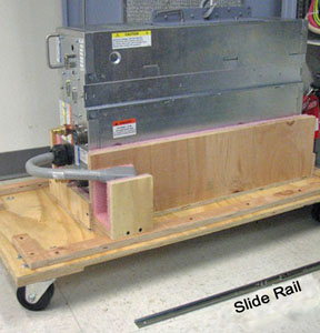
- Push the back end of the slide rail to unlatch the cabinet's
slide rails from the XPS unit. You may want to use a screwdriver to
unlatch the slide rail. After it is unlatched, release the cabinet
slide rails, and slide them into the cabinet. (The cabinet rails are
a reverse image of each other.)
Figure 8. Slide Rail Latch Removal
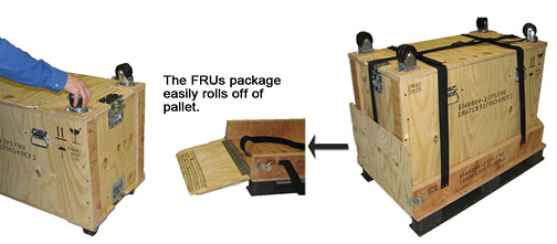
- The FRU is packaged in a wooden crate. Remove the top of the
wooden crate and turn it on its base. Roll the top under the XPS unit,
and lock the wheels so the container does not move.
Figure 9. FRU Package
- Ratchet the winch to lower the XPS unit onto the top of the
wooden crate.
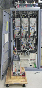
Figure 10. XPS Unit on Crate in Front of PGR Cabinet
- After it is lowered, unscrew the side rails from both sides
of the XPS unit.
Figure 11. Slide Rails Removed from XPS Unit
- Remove the hook from the lifting bracket.
- Unscrew the lifting bracket from the top of the XPS unit and roll the removed XPS unit to the side. Before returning the unit, purge the coolant as described in the Finalization section. Failure to purge coolant before shipping can result in freezing during transit, which can cause severe and permanent damage to the unit.
- Remove the center section of the FRU crate and set aside. It is used to package the removed XPS unit.
- Bring the FRU package with the new XPS unit to the front of the cabinet. Connect the slide rails to the new unit.
- Screw the lifting bracket to the top of the new XPS unit.
- warning
- Hook the lifting bracket on the new XPS unit to the hoist kit.
- Ratchet the winch to tighten the chains and begin lifting the unit. Slide the rail out a short distance to see how high to lift the new XPS unit. The slide rails of the XPS unit and PGR cabinet must align for correct insertion.
- When the slide rails are aligned, pull them out a short distance to get each side started. After both of the slide rails are attached, pull the XPS unit out until you hear a click, indicating that the XPS unit is docked in the rails.
- Ensure the XPS unit is secured on the rails, and slightly loosen
the chains with the winch to allow some freedom of movement.
- Make sure the cables are clear before inserting the XPS unit.
- Press in both release tabs, and begin to slide the XPS unit in until only the top of the unit is exposed.
- Unhook the hoist kit from the lifting bracket, and remove the
lifting bracket from the top of the new XPS unit.
Place the lifting bracket onto the XPS FRU crate with the four screws attached to the lifting bracket, as shown in Figure 5.
- Slide the XPS unit completely into the PGR cabinet, and reattach the module retaining bracket (removed from the old XPS unit).
- Connect the cables to the new unit.note:
If you are installing a new XPS unit (not an XP2), the dual fiber-optic cable may be difficult to reinsert into the new XPS unit. (The connector for the XP2 has been designed to eliminate this issue.)
Do not remove the SPF module from the XPS unit.
To connect the fiber-optic cable, insert the dual fiber-optic cable into the SPF module in the XPS by gripping either side of the hard plastic connector housing at the black section and then firmly pushing the connector into the SPF module until the connector clicks into place. Do not grip the molded plastic boot sections where the fiber-optic cables enter the connector.
If the cable is inserted backwards, it will not go in all the way.
- Disassemble the hoist kit (see Hoist Service Kit and Lifting Accessories).
- Return the main lifting beam to the PGR cabinet.
- After the beam is secure, reconnect the XPS J9 connector, and return the support tube to the HEC.
 |
 |
|
Finalization
- Remove LOTO from the PGR cabinet. See the MR Service Safety Manual, PN 5452735.
- Turn on the PPMP circuit breaker at the HEC. Start the pump by pressing ▲ F3 simultaneously.
- Run the DQA II tool to verify proper gradient polarities and adjust gradient calibration. (See DQA II Tool and Troubleshooting.)
- Recommended: Perform a Save-Info to capture new gradient calibration values.
- Remove coolant from the XPS unit being returned using the manual coolant removal kit included with the HEC. (See Coolant Draining.)
- Dispose of used towels according to local disposal standards.
- Attach the center of the FRU package to the removed FRU unit base. Then attach the top of the FRU crate to prepare the FRU for return.