- id_12373293
- Version: 1.8
- Date: Jul 5, 2019 6:08:29 PM
1.5T RF Amplifier Replacement
Prerequisites
| Required persons | Preliminary requirements | Procedure | Finalization |
|---|---|---|---|
| 1 | Not Applicable | 70 minutes | 120 minutes |
| Item | Quantity | Effectivity | Part number | Manufacturer |
|---|---|---|---|---|
| Safety Glasses | As needed | - | - | - |
| Work Gloves | As needed | - | - | - |
| MR Equipment Room Hoist Kit | 1 | - |
5196226 |
- |
| Non-Magnetic Tool Kit | 1 | - |
5113258 |
- |
| Item | Quantity | Effectivity | Part number | Manufacturer |
|---|---|---|---|---|
| Cable ties | As needed | - | - | - |
| Item | Quantity | Effectivity | Part number | Manufacturer |
|---|---|---|---|---|
| 1.5T RF Amplifier | 1 | systems with SRFD2 RF Amplifier P/N 2230683 |
2351573 |
- |
| 1.5T XRFD RF Amplifier | 1 | systems with XRFD RF Amplifier P/N 5317905-16 |
5317905-17 |
- |
| XRFD RF Amplifier | 1 | - |
5317905-16 |
- |
| Hoist Bracket | 2 | - |
5262278 |
- |
| Shipping Container | 1 | - |
543551 |
- |
|

| Condition | Reference | Effectivity |
|---|---|---|
|
The PGR PDU/gradient subsystem must be locked out and tagged out (LOTO) before starting this procedure. |
- | - |
Overview
There are three versions of the PGR cabinet. The table below shows which procedure to use to replace the RF amplifier.
| For PGR Cabinet Containing: | See Illustration: | Use Procedure In: |
| Power Distribution Module (PDM), Cronus Chassis, and SRFD2 RF amplifier (P/N 2230683) | Figure 1 | Systems with PDM, Cronus Chassis, and SRFD2 Amplifier |
| No PDM, but has Cronus Chassis and SRFD2 RF amplifier (P/N 2230683) | Figure 2 | Systems with Cronus Chassis and SRFD2 Amplifier (No PDM) |
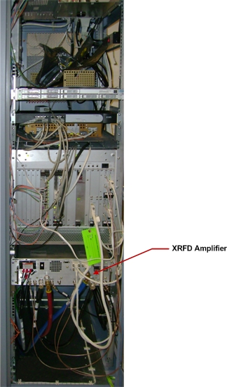
| No PDM or Cronus Chassis, but has XRFD RF amplifier (P/N 5317905-16) | Figure 3 | Systems with XRFD RF Amplifier |
Figure 1. 1.5T PGR Cabinet with PDM, Cronus Chassis, and SRFD2 Amplifier
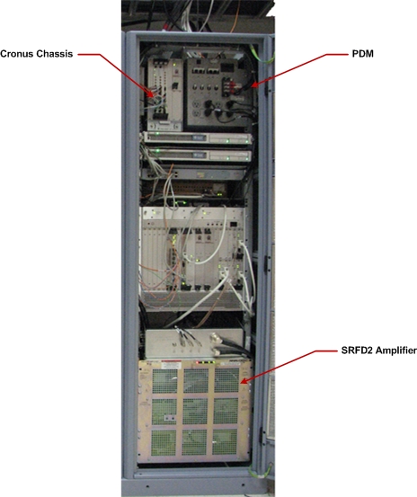
Figure 2. 1.5T PGR Cabinet with Cronus Chassis and SRFD2 Amplifier
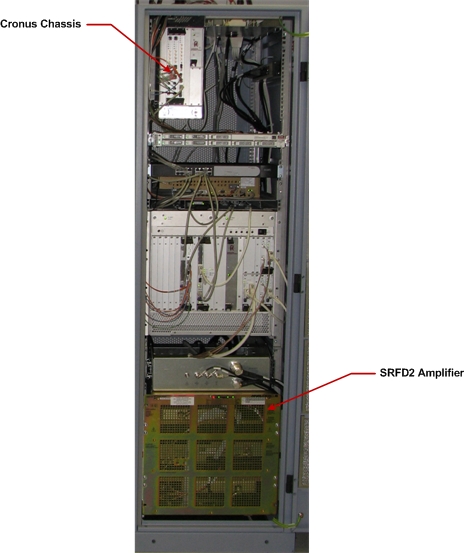
Figure 3. 1.5T PGR Cabinet with XRFD Amplifier
Systems with PDM, Cronus Chassis, and SRFD2 Amplifier
Removing SRFD2 Amplifier
Procedure
- Power down the host PC.
- Perform lockout/tagout (LOTO) on the PGR PDU/gradient subsystem. See the MR Service Safety Manual, PN 5452735.
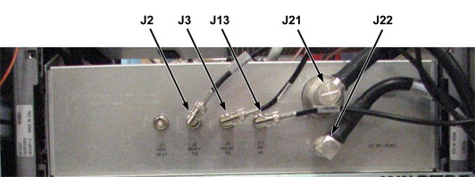
- Disconnect cables from J2, J3, J11, J21, and J22 on the RF amplifier
service bracket. Move these cables up and to the right of the service
bracket.
Figure 4. RF Amplifier Service Bracket
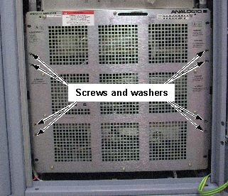
- Remove eight screws and washers securing the RF amplifier to
the cabinet mounting rails.
Figure 5. RF Amplifier Screw Locations
- Slide the RF amplifier and service bracket out of the PGR cabinet.note:
The sliding amplifier is a pinch hazard. Wear proper work gloves while performing this procedure.
- Remove tie wraps securing MGD/CAM cables to the service bracket.
- Cut the cable ties securing the power cable to the cabinet,
and remove the power cable from the cabinet.note:
The power cable remains secured to the rear of the RF amplifier. Note how this cable is routed in the cabinet.
- Mount the hoist service kit to the top of the RF side of the cabinet. See Hoist Service Kit and Lifting Accessories.
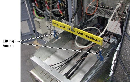
- Connect the lifting hooks from the hoist kit to the service
bracket.
Figure 6. Lifting Hooks Connected to Service Bracket
- Remove the tie wraps from the front of the service bracket. Move the cables going to the front of the MGD to behind the lifting hooks and spreader bar. This allows for the amplifier to be removed and placed on its skid without having to disconnect the cable from the MGD when removing the service bracket from the amplifier. (Cables may remain on top of the amplifier at this time.)
- Using the hoist, apply tension to the lifting chain until the weight of the amplifier is supported by the hoist.
- notice
- note:Cut the cable ties securing cables to the rear of the service bracket.
It is recommended that you cut the cable ties before disconnecting cables from the RF amplifier. This allows the amplifier to be fully removed from the cabinet, making it easier to disconnect cables from the amplifier.
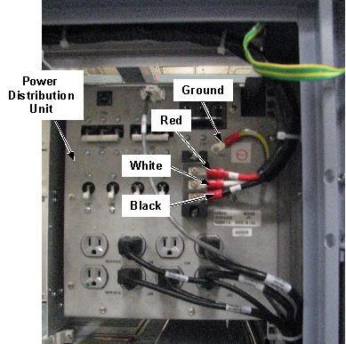
- From the power distribution module in the RF side of the cabinet,
disconnect the power cable from the mounting studs.
Figure 7. Power Cable Mounting Studs
- Remove eight screws securing the service bracket to the slide
rails.
Figure 8. Slide Rail Screw Locations
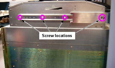 note:
note:One screw on each side is accessible through a hole in the slide rail. If necessary, you can remove the right side cabinet door for better access to the screw on that side.
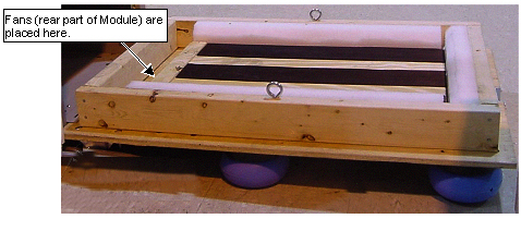
- Remove the top of the crate containing the replacement amplifier. The top of the crate for the replacement amplifier becomes the bottom of the crate for returning the failed amplifier.
- Place the removed crate top under the failed amplifier with
the pads facing the floor.
Figure 9. FRU Crate Top
- Using the hoist, lower the RF amplifier onto the crate top.
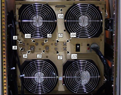
- Disconnect cables from J3, J4, J5, J6, J7, J8, J9, J10, J13,
J14, and J18 on the rear of the RF amplifier.
Figure 10. Cable Locations on RF Amplifier (Rear View)
- Disconnect the lifting hooks from the service bracket.
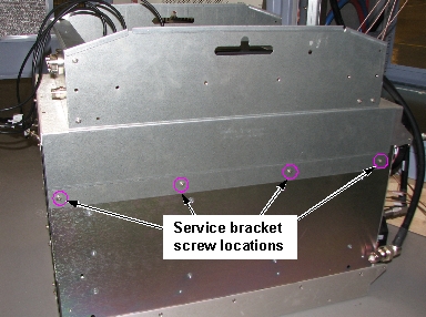
- Remove the service bracket from the RF amplifier by removing
eight screws.
Figure 11. Service Bracket Screw Locations
- Move the defective RF amplifier you removed away from the cabinet.
 |
Installing New SRFD2 Amplifier
Procedure
- Move the new RF amplifier near the cabinet. Attach the service bracket to the new RF amplifier using eight screws. See Figure 11.
- Connect the lifting hooks to the service bracket. See Figure 6.
- Using the hoist, lift the replacement RF amplifier up to the level where the holes for the rail mounting screws align with the holes on the slide rails.
- Route the power cable from the RF amplifier to the cabinet power
distribution module and connect the cable to the mounting studs. See Figure 7.note:
The cable routes inside of the slide rail for the RF amplifier, up the side of the cabinet, and then across the top of the cabinet. If you route the cable outside the mounting rail, you will not be able to slide the RF amplifier into the cabinet.
- Connect cables J3, J4, J5, J6, J7, J8, J9, J10, J13, J14, and J18 to the rear of the RF amplifier. See Figure 10.
- Secure the RF amplifier to the slide rails with eight screws.
- Remove the lifting hooks from the service bracket.
- Remove and stow the hoist service kit. See Hoist Service Kit and Lifting Accessories.
- Slide the RF amplifier into the cabinet, and secure it to the cabinet mounting rails with eight screws and washers.
- Connect cables J2, J3, J13, J21, and J22 to the front of the service bracket. See Figure 4.
- Secure the cables that were tied with cable ties.
- Go to the Step Finalization section.
Systems with Cronus Chassis and SRFD2 Amplifier (No PDM)
Removing SRFD2 Amplifier
Procedure
- Power down the host PC.
- Perform LOTO on the PGR PDU/gradient subsystem. See the MR Service Safety Manual, PN 5452735.
- Disconnect cables from J2, J3, J11, J21, and J22 on the RF amplifier
service bracket. Move these cables up and to the right of the service
bracket.
Figure 12. RF Amplifier Service Bracket
- Remove eight screws and washers securing the RF amplifier to
the cabinet mounting rails.
Figure 13. RF Amplifier Screw Locations
- Slide the RF amplifier and service bracket out of the PGR cabinet.note:
The sliding amplifier presents a pinch hazard. Wear proper work gloves while performing this procedure.
- Remove tie wraps securing MGD/CAM cables to the service bracket.
- Mount the hoist service kit to the top of the RF side of the cabinet. Refer to Hoist Service Kit and Lifting Accessories.
- Connect the lifting hooks from the hoist kit to the service
bracket.
Figure 14. Lifting Hooks Connected to Service Bracket
- Remove the tie wraps from the front of the service bracket. Move the cables going to the front of the MGD to behind the lifting hooks and spreader bar. This allows the amplifier to be removed and placed on its skid without having to disconnect the cable from the MGD when removing the service bracket from the amplifier in Step 18. (Cable may remain on top of the amplifier at this time.)
- Using the hoist, apply tension to the lifting chain until the weight of the amplifier is supported by the hoist.
- notice
- note:Cut the cable ties securing cables to the rear of the service bracket.
It is recommended that you cut the cable ties before disconnecting cables from the RF amplifier. This allows the amplifier to be fully removed from the cabinet, making it easier to disconnect cables from the amplifier.
- Remove eight screws securing the service bracket to the slide
rails.
Figure 15. Slide Rail Screw Locations
note:One screw on each side is accessible through a hole in the slide rail. If necessary, you can remove the right side cabinet door for better access to the screw on that side.
- Remove the top of the crate containing the replacement amplifier. The top of the crate for the replacement amplifier becomes the bottom of the crate for returning the failed amplifier.
- Place the removed crate top under the failed amplifier with
the pads facing the floor.
Figure 16. FRU Crate Top
- Using the hoist, lower the RF amplifier onto the crate top.
- Disconnect cables from J3, J4, J5, J6, J7, J8, J9, J10, J13,
J14, and J18 on the rear of the RF amplifier.
Figure 17. Cable Locations on RF Amplifier (Rear View)
- Disconnect the lifting hooks from the service bracket.
- Remove the service bracket from the RF amplifier by removing
eight screws.
Figure 18. Service Bracket Screw Locations
- Move the defective RF amplifier you removed away from the cabinet.
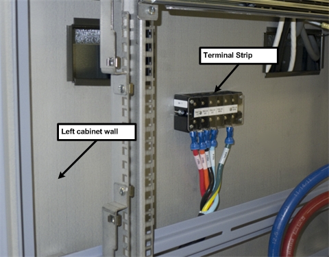
- Disconnect the power cable from the terminal strip located on
the left wall of the cabinet.
Figure 19. RF Amplifier Terminal Strip
|
Installing New SRFD2 Amplifier
Procedure
- Move the new RF amplifier near the cabinet and attach the service bracket to the new RF amplifier using eight screws. See Figure 18.
- Connect the power cable from the new RF amplifier to the cabinet terminal strip.
- Connect the lifting hooks to the service bracket. See Figure 14.
- Using the hoist, lift the replacement RF amplifier up to the level where the holes for the rail mounting screws align with the holes on the slide rails.
- Connect cables J3, J4, J5, J6, J7, J8, J10, J13, J14 and J18 to the rear of the RF amplifier. See Figure 17.
- Secure the RF amplifier to the slide rails with eight screws. See Figure 15.
- Remove the lifting hooks from the service bracket.
- Remove and stow the hoist service kit. See Hoist Service Kit and Lifting Accessories.
- Slide the RF amplifier into the cabinet, and secure it to the cabinet mounting rails with eight screws and washers. See Figure 13.
- Connect cables J2, J3, J13, J21, and J22 to the front of the service bracket. See Figure 12.
- Secure the cables that were tied with cable ties.
- Go to the Step Finalization section.
Systems with XRFD RF Amplifier
Removing XRFD Amplifier
Procedure
 caution
- Power down the host PC.
- note:Perform LOTO on the PGR PDU/gradient subsystem. See the MR Service Safety Manual, PN 5452735.
The lights on the amplifier will remain on for up to 10 seconds after power is locked out.
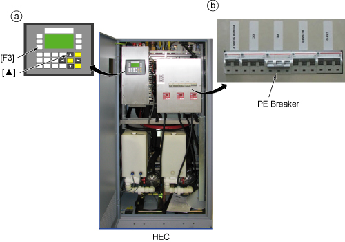
- Before disconnecting any coolant lines on the front of the RF
amplifier, shut down the Power Electronics Pump (PE) at the HEC by pressing ▲ and F3 simultaneously. Then switch the PE
circuit breaker to OFF.
Figure 20. Power Electronics Pump OFF
- Disconnect the coolant hoses from the XRFD amplifier. Wipe up any drips with a cloth.
- notice
- Drain the coolant from the XRFD amplifier. See Coolant Draining.
- Disconnect the cables from the XRFD amplifier. Move the disconnected
cables so the amplifier can slide freely out of the cabinet.note:
Remove the head transmit and body transmit cables last. If you require a wrench to remove these cables, take care to not damage other connectors on the front of the amplifier.
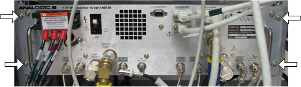
- Remove four screws and washers securing the XRFD amplifier to
the cabinet mounting rails.
Figure 21. Screw Locations for Securing RF Amplifier to Cabinet Rails
- caution
- Slide the XRFD amplifier out of the PGR cabinet.
- notice
- There are two hoist brackets included in the amplifier FRU.
Attach the hoist brackets to the top of the XRFD amplifier. Each bracket
is secured with three screws.
Figure 22. Hoist Bracket Screw Locations
- Mount the hoist service kit to the top of the RF side of the cabinet. Refer to Hoist Service Kit and Lifting Accessories.
- Connect the lifting hooks from the hoist kit to the service bracket.
- Using the hoist, apply tension to the lifting chain until the weight of the amplifier is supported by the hoist.
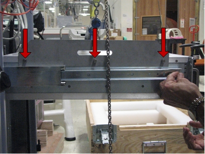
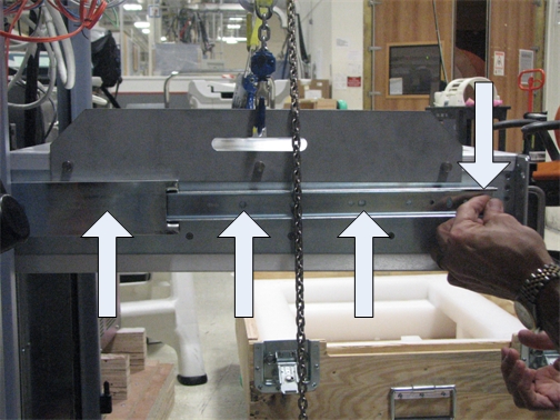
- Remove the eight screws securing the amplifier to the slide
rails. (The slide rails have holes that allows you to access the rearmost
screws securing the rails to the amplifier.)
Figure 23. Screw Locations for Slide Rails
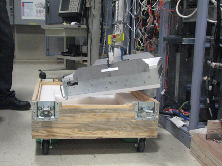
- Remove the top of the crate containing the replacement amplifier. The top of the crate for the replacement amplifier becomes the bottom of the crate for returning the failed amplifier.
- Using the hoist, lower the XRFD amplifier onto the crate top.
Figure 24. Lowering Amplifier onto FRU Crate Top
- Disconnect the lifting hooks from the service bracket.
- Remove the hoist brackets from the XRFD amplifier.
- Move the defective XRFD amplifier away from the cabinet.
|
|
Installing Replacement XRFD Amplifier
Procedure
- notice
- Move the new XRFD amplifier near the cabinet and attach the hoist brackets to the new RF amplifier using three screws per bracket. See Figure 22.
- Connect the lifting hooks to the hoist brackets.
- Using the hoist, lift the replacement XRFD amplifier up to the level where the holes for the rail mounting screws align with the holes on the slide rails.
- Secure the XRFD amplifier to the slide rails with six screws. See Figure 23.
- Remove the lifting hooks from the hoist brackets.
- Remove the hoist brackets from the XRFD amplifier by removing six screws. See Figure 22.
- Remove and stow the hoist service kit. See Hoist Service Kit and Lifting Accessories.
- Slide the XRFD amplifier into the cabinet, and secure it to the cabinet mounting rails. See Figure 21.
- Connect the cables and coolant hoses to front of the new XRFD amplifier.
- Turn on the PPMP CB at the HEC. Start the pump by pressing ▲ and F3 simultaneously.
|
Finalization
Procedure
- Remove LOTO from the PGR PDU/gradient subsystem. See the MR Service Safety Manual, PN 5452735.
- Power up the host PC.
- Calibrate the RF amplifier.
- Perform UPM Calibration and UPM Functional Check – Body Mode.
- Perform UPM Calibration and UPM Functional Check – Head Mode
- Perform a SaveInfo.