- id_2004431
- Version: 4.0
- Date: Apr 25, 2019 1:57:46 AM
Testing MRU
The MRU tester can be used to verify performance of the MRU/ERU during the yearly MRU test.
Prerequisites
| Personnel requirements | |||
|---|---|---|---|
| Required persons | Preliminary requirements | Procedure | Finalization |
| 1 | 10 minutes | 20 minutes | 5 minutes |
| Tools and test equipment | |||
|---|---|---|---|
| Item | Quantity | Part number | Manufacturer |
| MRU Tester Assembly | 1 | 5730424 | - |
| Digital Voltmeter (DVM) | 1 | 46-194427P284 | - |
| Safety |
|---|
|
Before working in any GE Healthcare MR suite or performing any GE Healthcare service procedure, you must:
If you have any safety concerns at any time, do not begin work or immediately stop work and move to a safe location. Immediately contact your supervisor or site safety officer for instructions on how to proceed. |
|
important:
Observe the following:
|
The MRU tester consists of the following:
- Resistor that simulates the load of the magnet heater (similar to the manual resistor).
- Switch that allows you to toggle between heater circuit A and B.
- LEDs that indicate voltage output to applicable heater (either A or B).
- Jacks for voltmeter connections.
- Cable to connect to MRU output.
- Input for MRU cable that connects to the magnet.
- The MRU tester can be used in place of the manual resistor that is currently referenced in the MRU vendor manuals. There is one resistor within the MRU tester. The switch will toggle between A and B MRU outputs. The jacks for the digital voltmeter (DVM) will provide the voltage output for either the A or B output, depending on the switch position. When the RUNDOWN button is depressed, the LEDs (both A and B) on the MRU tester should illuminate which indicates proper MRU output.
Procedure
- important: Failure to properly configure MRU tester could result in a magnet quench.note: This process is used to replace the resistor test that is found in the MRU vendor manuals.Open MRU.
- Disconnect the 4 pin Limo cable P2 at J2 of MRU.
- Plug MRU tester cable J2 into MRU.
Figure 1. MRU tester connected to MRU
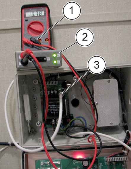
1 DVM 2 MRU tester 3 Cable - Plug DVM into jacks of MRU tester and check for proper voltage. Initial voltage should be zero VDC.
- With cable to magnet disconnected and MRU tester plugged into MRU, press the red quench or RUNDOWN button.
- Both LEDs on the MRU tester should light for a minimum of 30 seconds. The voltage should be approximately 20 VDC. This indicates proper operation of the MRU. If only one of the LED lights up, troubleshoot the problem.
Figure 2. MRU tester indicating open circuit
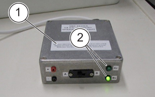
1 Tester 2 LEDs - Record voltages on PM forms for both A and B positions. The A/B switch can be toggled during the test to be able to record voltages for both A and B outputs. Eventually the RUNDOWN button will retract, at this time output voltage should be 0VDC.
- When complete, press Reset on the MRU. The Heater Activated LED should turn off. See applicable vendor manual for specific MRU to locate the Reset button.
- important: Do not connect cable P2 into the MRU if the LEDs on the MRU tester are illuminated, as this will cause a magnet quench.Remove MRU tester and re-connect cable P2 into the MRU.
- Proceed to Finalization.