- id_13106291
- Version: 3.0
- Date: Aug 29, 2019 1:46:27 AM
ECG leads installation and functional check
Prerequisites
| Required persons | Preliminary requirements | Procedure | Finalization |
|---|---|---|---|
| 1 | Not Applicable | 5 minutes | Not Applicable |
| Item | Quantity | Effectivity | Part number | Manufacturer |
|---|---|---|---|---|
| Ohmmeter | 1 | - | - | - |
Test Functionality of ECG Leads
Procedure
- If not already done, disconnect the ECG cables from the PAC
and from each other.
Figure 1. PIN Diagram of ECG Lead
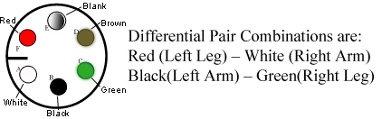
- Check the impedance of the ECG cables from each of the leads at point A to the other end of that lead at point B. It should be 60k ohms ±5% tolerance.
- Check the impedance of the ECG cables from each lead at point
B to its respective connection at point C. The impedance should be
0 ohms.
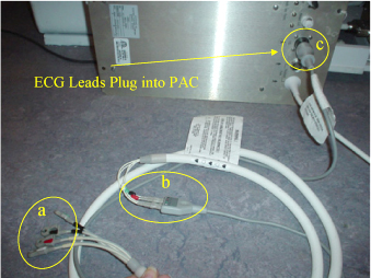
Figure 2. PAC Assembly with ECG Leads Connected
Connect Leads and Plug ECG Leads to PAC
Procedure
- Connect the white high impedance MRI ECG lead wires to the gray ECG patient cable by matching the colors on the white cable to the colored dots on the gray cable.
- Plug the open end of the gray ECG patient cable into the ECG port of the PAC. (See Figure 2.)
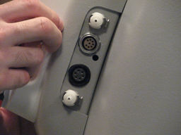
- Connect the ECG lead to the port located on the patient monitor
hook on left side of the magnet.
Figure 3. Port on Patient Monitor Hook
Finalization
Procedure
- Return the system to patient scanning condition.
- Complete Doing a check scan to ensure the system is operating properly.