- id_12374681
- Version: 4.1
- Date: Jan 17, 2020 11:16:43 AM
Emergency stop and off check
Prerequisites
| Required persons | Preliminary requirements | Procedure | Finalization |
|---|---|---|---|
| 1 | Not Applicable | Not Applicable | Not Applicable |
Overview
This document provides the procedure for checking:
- The EMERGENCY STOP function of the Power Distribution Unit (PDU) for the Gradient subsystem, and RF subsystem.
- The EMERGENCY OFF function of the power for the entire system.
The PDU EMERGENCY STOP buttons are located on the Operator Workspace Keyboard and on the Magnet Enclosure front cover (two buttons, left and right). A SYSTEM OFF button is located on the System Main Disconnect Panel. The other EMERGENCY OFF buttons are located by the customer.
System shutdown
- Launch the Service Desktop Manager.
- Click the Tools button and then choose System Shutdown from the Tools drop-down menu.
Figure 1. Service tools menu
 note: Shutting down the system as indicated above also shuts down the ICNs.
Emergency stop
Procedure
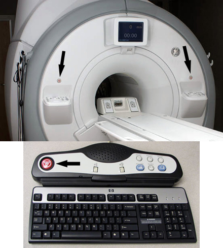
- Press one of the EMERGENCY STOP buttons
shown in the following illustration.
Figure 2. Emergency stop buttons
- Verify the power to the Gradient subsystem and RF subsystem
is shut off.
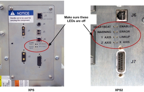
- Gradient verification: Look at the XPS (Gradient Power Supply)
Signal Board and confirm all four of the LEDs are off (see Figure 3).
Figure 3. XPS LEDs
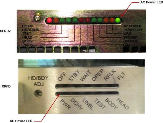
- RF Amplifier Verification: Look at the bank on the front of
the RF Amp and confirm that the AC Power LED is off. (See Figure 4).note:
It can take up to ten seconds for the XRFD RF Amplifier to power down completely.
Figure 4. AC power LED
 note: Activation of the Emergency Stop Button for the PGR cabinet will remove the high voltage from the gradient power supply and the RF Amplifier. However, be aware that the PDU voltage will stay enabled in the PGR cabinet after the Emergency Stop Button is pressed.
- Gradient verification: Look at the XPS (Gradient Power Supply)
Signal Board and confirm all four of the LEDs are off (see Figure 3).
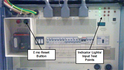
- On the PDU, press the EMO Reset Button to return power to all
affected cabinets. See Figure 5 for PGR PDU.note: When you press the EMO Reset button, you should hear the contactor engage. This is another indication that the E-Stop was pressed and is active.
Figure 5. EMO reset and input test points
- Repeat the steps in this section for each of the other EMERGENCY STOP buttons.
Emergency off
The AC power for the Magnet Monitor is not controlled by the Emergency Off button.
Procedure
- Make sure the Host PC and ICNs are shutdown. See System shutdown.
- Press one of the EMERGENCY OFF buttons (the location of buttons is determined by the customer). Verify that power was removed from the PDU by checking the input voltage test points or viewing the PDU power indicator lights. See Figure 5.
- Turn off the breakers for the Host and ICNs if you are testing
more Emergency Off buttons. note: If you do not turn off the breakers, the Host and ICNs will restart when power is enabled again, and you will need to wait for them to boot before you can test the additional Emergency Off buttons.
- On the System Main Disconnect Panel, press the SYSTEM ON button.
- Reset the On switch.
- On the PDU, press the EMO RESET button.
- Repeat Step 2 through Step 4 for the other EMERGENCY OFF buttons. (This includes pressing the SYSTEM OFF button on the MDP). Normal locations for EMERGENCY OFF buttons are in the magnet room and in the operator room.
Finalization
Finalization
Run the Doing a check scan procedure to make sure the system is functioning normally.