- Optima MR450w BASE 1.5T System Service Methods
- 5690012-2EN Revision 3
- 00000018WIA30B15450GYZ
- id_20222141.5
- Jun 11, 2021 2:25:52 PM
Installing the rocker clamp, rod link connector, and shaft rocker
Installs the rocker clamp, rod link connector, and shaft rocker onto the patient table.
Prerequisites
| Personnel requirements | |||
|---|---|---|---|
| Required persons | Preliminary requirements | Procedure | Finalization |
| 1 | - | 10 minutes | - |
| Tools and test equipment | |||
|---|---|---|---|
| Item | Quantity | Part number | Manufacturer |
| Nonmagnetic Titanium Service Tool Kit, Small Set | 1 | 5113258 | - |
Procedure
- If the rocker clamp was removed, install the two E-clips securing it to the table base.
Figure 1. Rocker Clamp E-Clips (GEM) 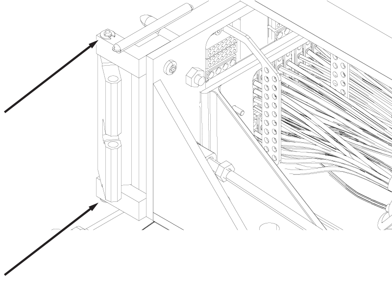
Figure 2. Rocker Clamp Removal (Non-GEM) 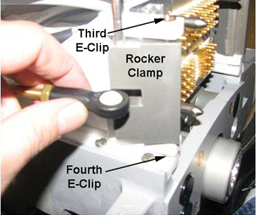
- Install the the shaft rocker and the two E-clips securing the shaft rocker to the front of the link rod connector.
Figure 3. E-Clips on Shaft Rocker (GEM) 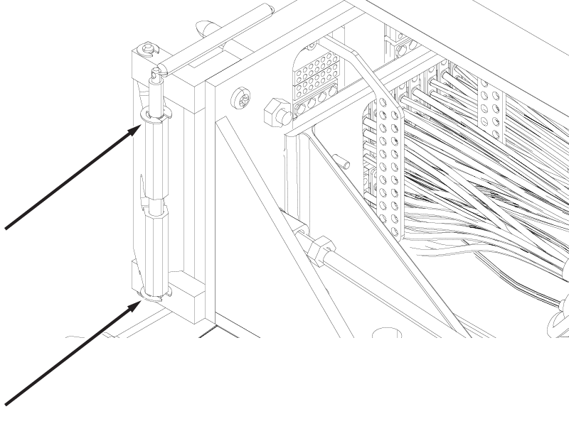
Figure 4. E-Clips on Shaft Rocker (Non-GEM) 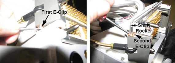
- Install the back portion of the rod link connector and the inner E-clip.
Figure 5. Rod Link Connector Installation 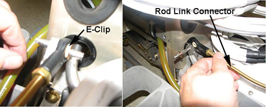
- Install the spring and the pin on the rod link connector.
Figure 6. Spring and Pin on Rod Link Connector (GEM) 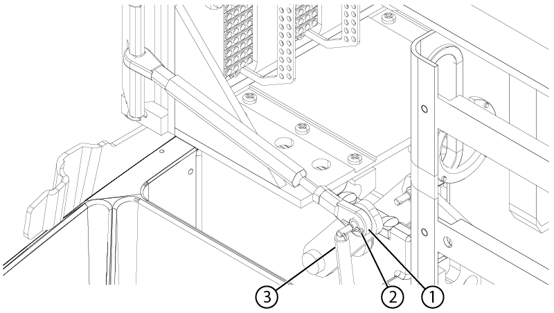
1 Link rod connector 2 Pin 3 Spring Figure 7. Spring and Pin on Rod Link Connector (Non-GEM) 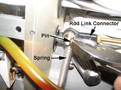
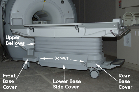
- Install the four screws (shown below) that secure the rear base cover to the table base and the bellows.
Figure 8. Screws Securing Rear Base Cover 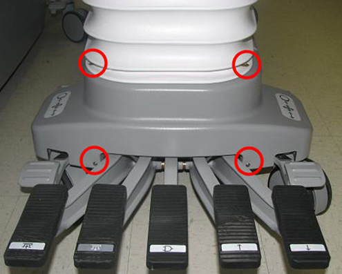
- Install the two screws that fasten the left and right lower base side covers to the table.
Figure 9. Patient Table Covers (Left Side Shown)